Showing posts with label DIY. Show all posts

Friday, April 18, 2014

3D printing using NinjaFlex with Makerbot Replicator2 and RepRap Prusa Mendel i3 Durbie v2

3D printing using NinjaFlex with Makerbot Replicator2 and RepRap Prusa Mendel i3 Durbie v2

Earlier in February, yours truly came across an exciting new type of 3D printing filament that is flexible, stretchable, thus allows for many creative creations. Say farewell to the rigidity of PLA and ABS! Without hesitance, yours truly ordered a spool of 1.75mm white filament with a local vendor (probably the first spool brought in here) at SGD100 per pop.
May I present to you, the NinjaFlex by Fennel Drives http://www.fennerdrives.com/ninjaflex3dprinting/_/3d/ .
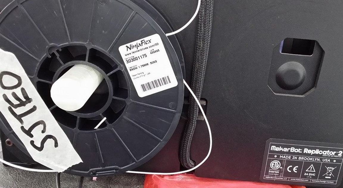
Finally over the last few days, yours truly manage to find some time to play with this excellent new type of filament. Prior to commit, it is best to read the manufacturer’s website and adafruit’s tutorial, and by following the recommended best practices for 3D printing with this NinjaFlex should be a breeze. Technically I summarized from the reading materials, if I followed the recommended extruder temperature of 215degC, non heated bed, and blue tape on the printing bed; it is going to be minimal effort to install the NinjaFlex and we can have a lot of creative fun happening here at FabLab@SP.
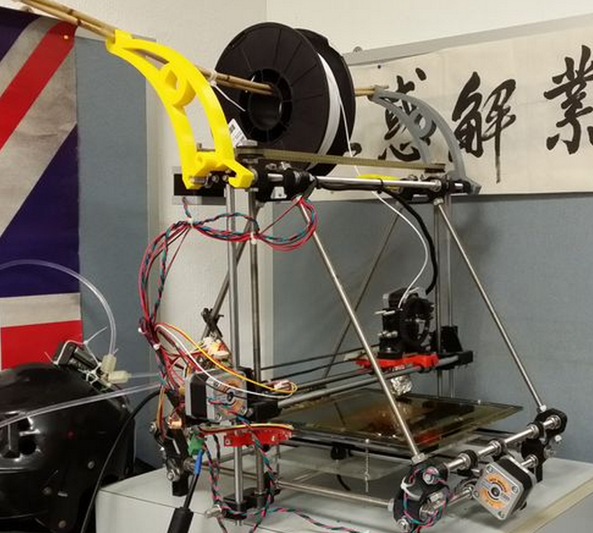
Sorry to throw in the wet blanket. The experiment with NinjaFlex is not a breeze, even with the prior knowledge well versed; hence there is a need to raise some awareness and share some experience on how to get it right (or way wrong) with NinjaFlex. Courtesy of FabLab@SP, yours truly has the luxury of tens of makerbot replicator2 at his disposal, and a well-stocked personal arsenal; you guess what, it consist of a 3D printer the RepRap Prusa Mendel i3 Durbie v2
Few important parameters that decide the success rate of 3D printing with NinjaFlex: filament feeder mechanism (FFM), extruder hot end (EHE) temperature, heated printer bed (HPB) temperature, type of tape used on printer bed, and extruder extruding speed (EES). Gathering from the reading material over the Internet, NinjaFlex has a specific operating temperature; users reported success with EHE set at 215 to 225 degC, and HPB set at 30 to 50degC. The filament is flexible and stretchable, sticks well to kapton tape; others reported success on blue tape, scotch tape, and acrylic. However, due to the partiality of info provided by various users that reported success, it is difficult to replicate their success at our end.
Hence yours truly has done several A/B test for NinjaFlex on both makerbot replicator2 and reprap, and varying the parameters.
Experiment1: NinjaFlex 3D printing with Makerbot replicator2 using modified MK2 FFM, non HPB, blue tape on printer bed.
All the makerbot replicator2 in FabLab@SP are modified with spring loaded FFM, as depicted in the picture above. Spring loaded FFM is the must have to print NinjaFlex on makerbot replicator. All parameters such as EHE at 218degC, non HPB, blue-tape on printer bed, EES at 40mm/s are held constant. On first try or maybe it is beginner’s luck, NinjaFlex is loaded successfully, FFM is feeding NinjaFlex with no qualms during loading phase. Next, when it comes to 3D printing with NinjaFlex, the material refuses to stick on the existing printer bed with blue tape, thus excess material clogged the nozzle. Subsequent tries to print, no material is oozing from the nozzle. So, carry out the SOP of unloading the filament, and then clear any material that clog the hot end or drive gear chamber. The next many hours to reload the NinjaFlex are frustrating. First of all, the filament itself is limp, lack the stiffness of PLA, thus it is becoming increasingly difficult to fish the filament through the guide hole. Even though the filament is fished properly through the guide hole, but no material is extruded through the nozzle. The filament is fed continuously in the whole process alright, but somehow, nothing is extruded. Open up the extruder to check for any jammed material at the hole entering the hot end, nothing. So basically the couple of hours are spent on repetitive cycle trying to load the NinjaFlex. The next logical step is to observe ninjaflex filament feeding into the extruder without the heat sink and fan. Surprise!! The filament is winding up in the drive gear. So to conclude this experiment: ninjaflex does not stick to blue tape, filament is too limp to be fed 100% correctly.
Experiment2: NinjaFlex 3D printing with RepRap Prusa Mendel i3 Durbie v2, HPB, kapton tape on printer bed.
All parameters such as EHE at 218degC, HPB at 40degC, kapton tape on printer bed, EES at 40mm/s are held constant.
Due to the design of the geared extruder, loading the limp filament is a breeze compared to makerbot replicator2. All need to be done basically to loosen the 2 spring loaded screws, manually fish the filament through the guide holes and also into the hot end, tighten the screws and then extrude filament to check for proper feed.
On the first try to print, the ninjaflex did sticks very well indeed to kapton tape. Besides kapton tape, subsequent tries on HPB’s glass plate but without kapton tape sticks well too.
3D Printing win NinjaFlex using RepRap went well. All is left is to fine tune the parameters to achieve the ideal result. Cone on the right is first try, left is second try.
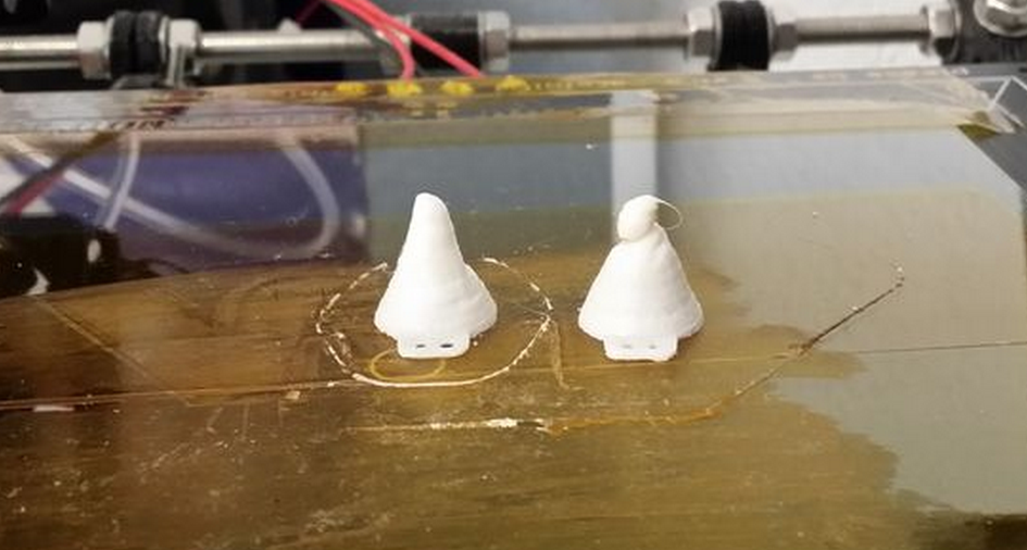
Once the 3D printing parameters are tune with confidence, try it on a bigger print job to check whether 3D printing NinjaFlex with RepRap lives up to it’s reputation. The parameters used are EHE at 220degC, HPB at 40degC, kapton tape on printer bed, EES at 20mm/s. The following parameter is peculiar only to slic3r for ninjaFlex: Fill pattern rectilinear, Infill 50%, 3 shells, 4 skirt loops, layer height 0.2mm,
The first few layers printed according to expectations, however, half way through a 3hour print job of a note3 bumper, the ninjaflex filament is not feeding and starts to air printing. After a few tries with the smaller test prints, apparently the nozzle clogs at random layers and hence air printing too.
While issuing a new test prints, out of sudden the reprap is not printing and pronterface can’t connect to the reprap. First, the ninjaflex is working only to air print randomly, then the reprap stop responding. The experimentation with NinjaFlex on reprap can’t be continued, until the issue with RepRap is resolved. What a bad day to do experiment. The semi conclusion will be NinjaFlex sticks well to kapton (and also glass panel tested before the RepRap went cold), printing with RepRap is a breeze; but need to resolve the air printing.
Experiment3: NinjaFlex 3D printing with Makerbot replicator2 using modified flexMK8 FFM, non HPB, blue tape on half of printer bed, and the other half is clear acrylic.
For experiment1, the suggestion is to find a better spring loaded FFM that ensures 100% chance of feeding the NinjaFlex into the hot end of the extruder. There is ready solution for open source printers, such as the lulzbot flexystruder http://www.lulzbot.com/products/flexystruder-tool-head tailored specifically for NinjaFlex type of filaments. However, not suitable for makerbot replicator2. I guess the good people at fennel drives are serious about their ninjaflex product, reads about the user comment on Internet and thus uploaded a FFM mod http://www.thingiverse.com/thing:169086/
This mod is very easy to install. Simply print out on the existing 3D printer, let it cool by turning off the power supply, and disassemble the existing FFM to be replaced with the flexMK8.
Loading of the NinjaFlex into Makerbot replicator2 could have been easier!!! It takes only a single try to load!
The parameters used are EHE at 220degC, non HPB, EES at 20mm/s. The following parameter is peculiar only to makerware for ninjaFlex: Infill 10%, 2 shells, layer height 0.2mm. As for the test print, see for yourself.
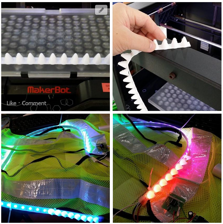
As suspected, NinjaFlex sticks better on clear acrylic than blue tape on printer bed.
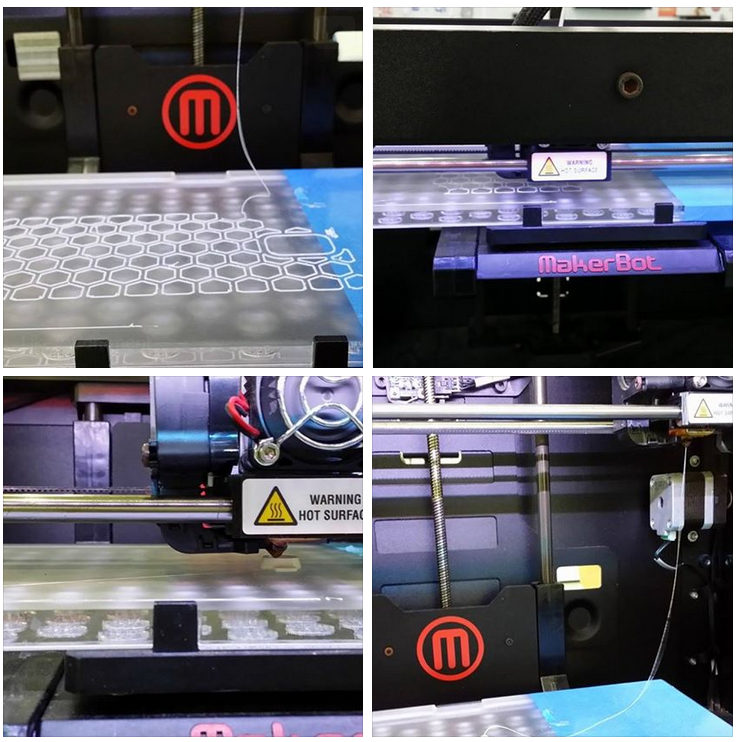
Confidence are built upon many unsuccessful experiments. The first big print job that takes 4 hours to complete with NinjaFlex.
Of course, the experiment with NinjaFlex comes complete with the adafruit cyberpunk spikes


Concluding experiment3: use flexMk8 with makerbot replicator2 for a successful loading, as for the parameters used are EHE at 220degC, non HPB, EES at 20mm/s. The following parameter is peculiar only to makerware for ninjaFlex: Infill 10%, 2 shells, layer height 0.2mm.
Outstanding task: fix the RepRap and then continue to find the best parameter to print NinjaFlex.
References

Monday, July 1, 2013

quick and dirty way wiring a K type thermocouple with LM358 op amp to replace LM35 on an Arduino

Personally, I prefer to use LM35 as my temperature sensor instead of anything else. The reason is simple, it is bountifully available in our tech arsenal (just a mouse click and I can collect it from block T8), it is very simple to use with no extra circuitry, precision at +- 0.5degC within 0degC to 100degC, and literary it is plug and play with arduino. check out my previous post  on getting started with LM35 and arduino. I am using this sensor for my arduino sousvide setup. After 6 months of abuse, it broke down, the waterproof temperature probe gave way, and water breached in it causing a short circuit. Shown below is my wiring for LM35; the optional 10K Resistor is there to suppress wiring capacitance that came with very long cables.


so my next course of resolution would be to get my hands on spare LM35, and also another method to water proof it. Little did I realise, a small little piece of LM35 is retailing at £1.99 per piece!  To add salt to the wound, a pathetically sized 6cm x 4cm veroboard (stripboard) cost me £1.69 after 50% discount. The price gave me a real shock in my life. I always assumed that ICs are dirt cheap. The other possible explanation is that I have been living in the tech tower with a wide variety of ICs, PCBs, EE components at my disposable to make projects, losing touch with the reality. Arghhhh, how i miss my staffs at the procurement office. Not because of the complicated purchasing process I constantly bang into, but their effort to make sure we are well stocked.

After much googling around and also posting messages on my facebook to BBS (beg borrow steal). I came across websites such as TI are giving samples for free. Since I am staying across the pond and have an expensive looking email address, I can get my hands on 3 type of ICs with 3 samples of each in an order for free, and with shipping included too. As a backup plan, I also ordered a some ICs to complement my K type thermocouple that I have ordered earlier on amazon for £2.93 with free shipping.


The plan is simple. Solder a LM35, stick it into a brass radiator key I have idling around, and seal it with sugru. Sugru is going for £8 per packet of 5 mini sachets. I only needed one. My prior experience  with sugru is a wasteful one. It has an expiry date that will be cured (harden) by than no matter what. Nonetheless, it is a good material to fix stuff. I posted a message on facebook group seeking partners to share the cost of materials; a kind soul from institute of making gave me 2 mini sachets for free!


Always test your equipment/stuff before sealing/cast in sugru or committing more materials on top of the equipment. In my case, i tested this waterproofed LM35 on my arduino before cooking an expensive piece of dry age beef. To my amusement, the temperature reading is fluctuating wildly. This is really bad signal to be the input for the PID control algorithm. It makes the tracking to the set point difficult and unreliable. To make the matter worst, the sealing of the edges on the brass radiator key with sugru did not went well as expected. When it is submerged in the water bath, I saw some air bubbles emerging from the thermo probe.

There can be a myriad of ways on what went wrong. leaky probe, faulty LM35, wiring capacitance that affects the reading, faulty pin on arduino etc etc. Thus, the great troubleshooting begins! I started off plug and play with another LM35 I soldered, but used a plastic bag instead for water proofing. Still the same old wildly fluctuating reading. After much troubleshooting and have exhausted all possible options, I tested the last piece of LM35 before solder and after solder. Ah-ha.... found the culprit. The solder iron is too hot for soldering ICs, and I have put it in contact with LM35 for too long a second.

Having busted 2 out of 3 of my LM35 and lost the 3rd in translation, I am back to my K type thermocouple. One reason that make me don't really like to use K type for my sousvide setup, is because it's temperature range is very wide, it is ranging from -260degC to 1400degC (manufacturer dependent). Divide the temperature range with 5v and than you will get what I mean. Reasons not listed exhaustively for my dislike include the requirement of a cold point compensation circuit for precision; signal output is in the range of milivolts per degC; it need an amplifier circuit to work, and can't connect directly to arduino; the amplification is not exactly linear for a cheapo amplifier which makes the code complicated to work with the circuitry; adafruit Thermocouple Amplifier MAX31855 breakout board going to cost me £16.80 from a UK dealer; and the list goes on.

Having said that, a very simple op-amp with a gain in the range of 100 would easily fit the bill for my setup with K type thermocouple. I just need to figure out the output voltage in milivolts of my k type thermocouple would output at the desired temperature for cooking, amplify it and normalized it to the temperature in degC. The first step is a re-visit to the data sheet of a LM358 IC, something I have not done for some time. To be frank, these ICs data sheets are not written for the layman in mind. Reading the data sheet not knowing what you need or a how to get things done will surely put off many people and abandon the project (not as if their livelihood depends on it). Scrutinizing the data sheet in detail, I just wonder why it does not include the classic text book example of a N-gain amplifier. I forsee that layman looking for something quick and fast through the data sheet will be disapointed and will spent hours trawling the internet for usable bits of info. How many will give up half way or abandon their project in due course of looking up for information?

The quick and dirty way of wiring of LM358 is at the self explanatory figure below, drawn by hand from yours truly.


B-side of the £1.69 veroboard. I still remember what was taught in my digital electronics class many years back. The hint is in the picture below.


Putting everything together for action. no smoke, no sparks. phewwww


I noticed the reading of the k type thermo couple from the LCD with comparison to my trusty digital thermometer. The final temperature read by K type thermocouple with LM358 is always biased at about 9 to 10 degC. This render the previous code useless. Nonetheless, it is easy to fix.

The only modification to the source code, from the code meant for
LM35-> temperature = (5.0*val*100/1024);
 is modified to
LM358-> temperature = (val+9.5);

ARGHHHHH.... can you smell what the ROXXX is cooking?!

Monday, December 31, 2012

coming to an end of 2012

A self reflection??!! I just remembered to write about the sous vide stuff with Arduino. (BRING ON THE YUMMEH) DIY arduino Sous vide shield + code + cooking + ACTION
close up shot
The setup. I am using my HTC desire phone charger to power on the system instead. When i am using my 12V 1A DC supply from the wall, the temperature reading is way crazy. SUPRISE!! I am getting readings with very wide fluctuations. The LM35 is power by the 5V from the arduino. I suspect is the onboard voltage regulator might be giving way, but no way to verify because I do not have a digital multimeter with me now. When development was done, it was supply with 5V USB from a laptop. It is important to test your system with both the intended supply and also the USB supply. sous vide lamb shoulder 57degC for 24hour.
sous vide beef brisket 75 degC for 24 hour
Details of making this shield, check out the instructables by my padawans (keyou + suan) Instructables Here code here

Thursday, October 11, 2012

repartition disk ubuntu 12.04 in vmware with GParted

I was playing with my linux and unix VMs (vmware workstation 9) to setup for my lab environment, for the purpose of my lab session. I am surviving with only my dell XPS which runs on win7 Enterprise :( While playing setting up, there were 2 main obstacles that made me a "dumbledore"  moment.

In this session, I shall highlight the guide to solve one of the obstacles. The other is with wxwidget, which I will cover soon.

When I was creating a VM for ubuntu 12.04, at the option to select disk space, I only create a VMDK of only 4GB. This is because I am trying to save on the HDD space on my dell XPS. Installation went well, until i booted up and start to compile and run my code. To my horror, my free space in ubuntu is left with 127MB, that is after several sudo apt-get of the necessary software. A quick df -h showed me the details of the HDD space use.  Therefore, I need to increase the VMDK size (by 1GB hahaha... I am damn ngiao[petty] OK!).  

Few steps to complete this.
1. Power off the guest OS VM (e.g Ubuntu 12.04). 
2. Change the Hardware setting of the VM to XXX GB (as required).
3. Download GParted iso (opensource disk utility) on the host OS.
4. Power on guest OS VM
5. mount 3. 
6. restart ubuntu 12.04 (click shutdown from dashboard, in the popup on the LHS, there is a restart)
7. while rebooting press F2 on the vm boot sequece to go into the pseudo bios scree.
8. change the boot sequence by moving CD Rom to the top (it contains the GParted) and save before exit
9. continue to boot as usual and you will be greeted by the GParted GUI (unless you have choosen otherwise during the startup dialog)
10. Use GParted to resize the partition and then reboot

the dumb moment..... I am trying to make sense out of the google research I did on using GParted at step10. None of the results user guides are detailed enough to help a layman (e.g me) to use it. After some experimentation based on the steps given by others and recalling my prior experience, I managed to deduce the steps to assign the unallocated space created from VM workstation and resize it to be larger.

**Rules of thumb: Never delete the boot partition on the LHS. Always compact the partition on the RHS of the boot partition by 1.Delete partition (s) to the RHS of the boot partition. 2. Combining unallocated space. 3. Resizing of boot partition will always take the unallocated space from the RHS of the boot partitition. 

Explore the partition information. In this screenshot from my VM, my unallocated is at the extreme RHS, which is not sequentially next to the boot partition. 


Right Click on linux swap partition, then click on information. Check that partition is swap-off (e.g the swap-on option is waiting for you to enable, DO NOT click it). Right click again to delete the linux swap partition (/dev/sda5) and then right click on /dev/sda2 to delete the extended partition. The final output will be the screen above. Note that my unallocated space became 2GB from 1 GB.
Right Click on the boot partition and click on resize. The popup window appeared to allow adjusting of the hdd size by sliding the vertical bar or changing the new size parameter. I leave 1GB for the linux swap partition. To finalize all the new settings, click on the OK button. 


Next, click on the remaining unallocated space and assign it to be extended partition, such that logical partition can be created in it. Review the lower window on the actions to be executed. Once finalize click on the apply button.


Fingers crossed.....


Reboot to guest OS and double check the size of the partition by issuing sudo fdisk -l


Monday, June 18, 2012

DIY D3 soulstone USB drive


My Student ThianB just bought the Collector's Edition for Diablo3. This game is all on the rage now. Well, the last time when i was playing D1 and D2, I still remember how obsessed I am with the game mechanism. Weirdly, D3 does not attract me that much.

After seeing ThainB posted his spoils online, I gave him a ring and request for a T-Loan. Shamelessly telling him that it is just a piece of plastic and I can and going to make a replica of the soulstone.  LOL
BEHOLD, soulstone and diablo in their full glory. The artwork of these 2 pieces of plastic toy are really well defined and detailed to the last milimeter. I first started out to use art-clay/plasticine to make a mold.
I found out that the material is too hard and not malleable on the surface. Hence loosing some of the detail or I risk breaking apart the toy.


As for the setting agent, I am using this GlobalCast A-B, balance from my previous project.

Pour 1:1, and then mixed thoroughly. It will set in 1hour time and takes 24hour to cure completely. Make sure all the safety precautions are observed. Such as wearing of gloves, safety goggles and proper foot wear.

Before pouring the mixed solution into the mold, ensure that there is no seepage. Take a look at my poor art work.


The mixed solution will turn from clear, to opaque and finally to white. Let it sit for 24hours before releasing from the mold.


Taking them out from the mold. It need some glue and filling off the rough edges.

Now, it is awaiting for a fresh coat of paint to look like the real McCoy, just to TROLL ThianB. LOL 


Tuesday, March 6, 2012

[arduino] Music to RGB with LOLSs

Just in case you guys wonder, the previous LOLSs suffers from oxidation, poor solder joints and frequent breakdown with intermittent connectivity. Lih Sheng + helmi had kindly solder another piece of it for my use. Not to forget Kay Jin for helping to fix the broken leads on the RGB LEDs . Thanks!~

As of the previous challenge #3 posted to the lads and lasses to make the RGB LED change colour according to music, sadly none came forward and show me their stuff! Why I got to do everything myself
:(

update Sept 2012 this project was incorporated on a headphone and featured at Singapore Maker Faire


Time is a rare commodity. It is very difficult to prioritize which should come first (interest, hobby, $, love, life, work). So to save time, we should reuse as much as possible of what the stuff we had done previously!

If you guys could still recall my Arduino VU spectrum analyzer with FFT using LOL shield, courtesy of Andy Doro. Ready code are available for converting analog data on time domain to frequency domain.

The tricky part is actualy "mapping" the amplitude of each frequency bands (14 bands in total, coded for the LOL shield) and for all of the frequency bands into RGB. To further make the matter more complicated, Amplitude transition within each frequency band should be represented with the intensity/lumen of the RGB via the use of PWM, follow by hue/fading when transition in-between frequency bands.  Courtesy of "akgraphics" for the hue controlled RGB, my this experiment was made slightly easier......

In other words, my idea is to
1. Arrange the frequency bands into 3 "groups", low mid and high frequency and "map" into R, G then B.
2. Amplitude of each frequency band would translate into the brightness/intensity of each colour using PWM
3. Cycling from one frequency band to another, the R<->G<->B would "fade" by changing the hue of each colour.

Now, for the connection part
Using a 3.5mm" stereo jack to tap audio signal from computer/smart phone into A0 of arduino.
PWN pin 9,10,11 are use for controlling the RGB. LOLSs (it has a darlington IC) is used to "switched" 12v for the RGB LED strip with PWM.


 Just a point to note, test your RGB LED first. One of the RGB LED is not functioning properly when the pin for Red is held logic high. Time to get more RGB LED strips.


SWEEEET! Not bad for the first iteration.


If you have notice from the video, the "mapping" of sound frequency to RGB is not ideal. I get mostly RED, yes RED LIGHT. It is going to be any EYE SORE if I would stick this LED strip on my cheapo headphone as a bling bling. More time is needed to discover the relationship between the frequency appeared in music and the relevant colour to represent it (through code, that is). *hint: use the serial monitor* Another thing to note, how to repackage it so small (code size is 6k only), easy to retrofit on existing headphones (I DIZZ pseudo DR.Dre beats/senheizer), battery operated etc. Did I mentioned $$$ making?! LOL

Here comes the SUGAR. It can be intimidating, but the comments should make you feel at ease. Feel free to use/modify and let's ROXXX! Share your findings. A ping on new discoveries are much appreciated.

Saturday, February 18, 2012

[wares]

Still remember my HDD hack back in 2009?

Last tuesday, my E8410 suffered a BSOD then followed by a core dump.
It din't managed to reboot after all that. Can't even complete the POST (Power On Self Test)

I have tried various troubleshooting sequence, trying to isolate the problem.
1. Ram, by swapping fresh rams.
2. Pull out the hdd and CDrom just to boot from bare machine

It has beeping sounds, with various sequence.
1 long 2 short
1 long 3 short
4 short
=============================================

FML, time to waste $$$ again.

Tuesday, February 7, 2012

[Arduino] 4x4x4 LED cube

I was really caught up with work, as always but I will try to update as frequent as possible.

back in 2009, I came across the idea of making 3x3x3 LED cube as part of the teaching material for programming, electronics , and leading the concept to computer engineering.
http://shin-ajaran.blogspot.com/2009/06/diy-3x3x3-led-cube.html

Now at late 2011/ early 2012 one of my project students, Eagle. He picked up the idea and superseded my 3x3x3 with his creation of 4x4x4 LED cube with some really awesome electronics circuit skills and soldering skills... that is soldering of 48LEDs into 3 layers, each layer consist of 16LEDs, with a XYZ+ (I lost count of it) solder joints.  IMBA!! To make life easier he is making this into an arduino shield for those that are interested to pick it up easily (minus the hassle of soldering, just plug and play).


Now hook it up to the arduino microcontroller. 4pins to control the layers , 4+4 pins to control the individual LEDs at each layer, 4 analog pins to control the dimming effect. Displaying of patterns on the LED cube requires the idea of refreshing the pattern at a high speed, to give human an illusion that there is animation. In actual fact, the LED just took turn to light up, one by one. 

now, code time. This code can be quite scary, looking at the binary pattern used to display the led pattern and using progmem to store the "animations". The code was adopted from an instructable.


The end product is totally worth the hours put in to this pet project! Check it out~


Next stage, would be modifying the circuit to use LED driver chip MAX7221. Luckily I bought some during my last visit to Shen Zhen.

I brought this LED cube around, like a young boy showing off his geeky toy. Upload to my facebook account just to attract some interest.... Little did I know, one of my programming class student surfaced with his 3x3x3 LED cube that he has made.... And the voyage to kernel begins...
check this out yo!

Friday, January 6, 2012

[FYP] Engineering Show 2012

My projects running Engineering Show 2012

Project: Interactive Video Wall


Project: Cloud Computing Software Loan Portal


Project: DIY PRT


Friday, October 7, 2011

[Arduino] Solid State Relay ( SSR )

[Arduino] Solid State Relay ( SSR )

Currently the DIY PRT prototype uses a HUMANGOUS 24V 10A mechanical relay + transistor circuit to switch between the 5V MCU digital pin and the 24V 10A DC supply to the motors.

In the next step of modularizing the building blocks of the DIY PRT into an Arduino Shield, that AWESOME relay could not fit into the shield. Worst part of it, the EM generated by the motors traversed the wirings and this affect the reading of the sensors. Previously, sparks was observed in the mechanical relay when the circuit turned on while the wheels were locked accidentally. If working in enclosed environment with dangerous gases (not fart pls), the spark might cause an explosion...Worst of it, there is no isolation of high current high voltage circuitry from the low voltage low current MCU. The circuit run a risk of frying the components at the low voltage low current side. Well, unless the opto-isolation circuit (opto-coupler) is included. The circuit get more and more complicated with each additional feature added!

The challenge here is to reduce the size of the relay, have opto-isolation and also simplify the circuit. SSR is here to the rescue~~~ http://en.wikipedia.org/wiki/Solid_state_relay
_________________________________________________________________________
One day while running some errands outside the office, I chance upon a SSR circuit from Mr.ChongSP’s D&I lab. It was displayed outside the lab.

Using my thick-skin-jutsu i approached the lab TSO and executed my BBS move on her. Mr.ChongSP and TSO Ms.Jana were more than happy to supply me a set of the SSR kit. thx! Look at the timestamp of the pictures, It took me more than a month to acquire, experiment and write down the experiment. Time is a rare commodity (exam, marking, checking, tallying, data entry, checking again)….If you have some spare CPU cycles, consider to supply me some.
The TSO reminded me that this PCB connection is meant for DC-DC switching from low voltage to not so high voltage.  But according to the specsheet of the omron SSR (I love omron relays!) http://www.omron.com/ecb/products/pdf/G3VM_351BE.pdf
This babe is capable of switching to 280V 100mA !!! Just to be safe, I only try to turn on a LED. lol. A quick peek at the specsheet, this babe is capable of switching DC-DC and also DC-AC depending on the configuration.
Soldering the PCB is pretty straight forward with the detail explanation on the silk screen. A point to note, when soldering ICs’ , never mount the IC to the IC holder while soldering the IC holder to the PCB. The heat form the solder might damaged the IC. An advise from my lab TSO many many years back when I was a student here. IMMA such a good student @@”
Only plug in the SSR when all the soldering is done.

Pretty neat huh...


Now, connect the GND pin from the PCB to GND pin on Arduino (I found some students make this mistake when wiring up stuffs... The consequences may range from very small such as circuit not working to very serious such as sparks and fried MCU), VCC pin to 5V on Arduino and lastly signal pin to any one of the digital output pins on the arduino.

As for the code, I use the example code found at File->Example->Digital->Blink.
The SSR will be triggered at specific interval, turning on the LED. Phew.... everything work at 1st try. Now, time to wire this SSR to more interesting hardware (<10 V load plssss). Interested to play with it ????? dXD