Friday, October 31, 2014

IoT inspired: multi plug modified with SSR for AC control with a microcontroller

Yours truly is no stranger to controlling AC (Alternate Current, not Air Condition) with the use of microcontroller based system. In the previous posts, there were several iterations of arduino sous vide; controlling a SSR (Solid State Relay) or mech Relay to on/off AC connected to the heating element via a digital output from the microcontroller.

Fancy using an smart phone app to control the AC electrical appliances e.g lighting over the Internet? No matter what are your motivation to  control AC with a microcontroller based system, then the setup below to control on AC appliance may satisfy.

The AC controlling circuit from the previous iterations are not elegant. The leads from AC are exposed, one way or the other. A wire exposed for termination posed a risk to the untrained. The following picture describes the exposed AC leads connecting to a microcontroller based system, even with the use of a terminal block.


The hazards are real: assuming a user touches the exposed end (circle in red in the picture above), or the wiring connection is loose, or worst,a stupid attempt at a cheap stunt.

Ever since the first inception of the microcontroller based AC control circuit, the search is on for the "perfect", fully enclosed, risk free implementation. On a casual saturday strolling along the street, yours truly chance upon a small tuck shop and a transparent multi plug with enough space to hold the SSR PCB https://www.sparkfun.com/products/10684 . The rest is history.

This implementation requires a multi plug, and a SSR PCB.

Warning: Potential hazard to human. Do not attempt this hack while multiplug is on a live connection. Do not attempt to touch the exposed ends when live. Ensure human is properly insulated from ground with rubber sole shoes.

1. Dismantle the multiplug, and make space for the SSR PCB


2. some electrical tape is used to insulate the exposed end from coming into contact with the SSR PCB


3. Drill a hole (circle in red) on the multi plug to accommodate 3 wires (VCC, GND, SIG) to the SSR PCB. Remove some of the brass contact (square in red) on the live wire connection. The remove ends will be soldered with wires to be connected to the SSR PCB. Use electrical tape as necessary to insulate the exposed ends.


4. Solder electrical wire to the exposed ends of the live connection, circled red in the picture below


5. Secure 3 signal wires (GND, VCC, SIG) to the SSR PCB through the hole made earlier.


side view of the multi plug


6. Examine, label, test. In the following picture, circled in red is where the live connection is broken, and then the exposed ends soldered with electrical wires. These wires are then secured on the LOAD side of the SSR PCB. Test this modification of the multi plug only on a live system that is equipped with a functional ELCB http://en.wikipedia.org/wiki/Earth_leakage_circuit_breaker


user view of the modified multi plug with SSR


6. Observations
This is not the most elegant solution yet. The electrical wires (multicore) suffer from wire fatigue; due to the constant wiggling, twisting, and securing to the connector in a very compact space within the multi plug. Nonetheless, there are no AC exposed ends that might posed a risk to the end user. Plug the VCC, GND, SIG wires to a microcontroller, load some IoT inspired code and now you are ready to control AC electrical appliance over the Internet.

IoT SSR multiplug in action; using D7 on arduino to on and off SSR at 1second interval


Thursday, September 4, 2014

cheapest U$5.97 DIY sous vide setup

Yours truly is no stranger to DIY sous vide setup, having dabble in various microncontroller based home made sous vide setup. The PID controlled arduino sous vide setup by yours truly can be found here http://shin-ajaran.blogspot.sg/2012/12/coming-to-end-of-2012.html. This PID controlled arduino sous vide has been instrumental in setting up for the perfect dinner dates with the missus. I have cooked fabulous steaks, short ribs, lamb racks, and the epitome of my DIY sous vide home cooking: the effortless Beef Rendang. Details of the beef rendang can be found here http://shin-ajaran.blogspot.sg/2013/08/beef-rendang-sous-vide-70degc-24-hours.html

After rubbing shoulders with humans at several maker faire, or maker inspired activities across the continents spanning many miles apart https://www.flickr.com/photos/uclengineering/11119871993/
humans often remarked: "it looks so complicated/dangerous/scary!", "I want to have one but I can't write the program/wire the electrical/solder the electronics", " i want to buy a commercial one/the parts/components, but it is out of my reach", etc.

After seeing a fellow foodie and sous vide enthusiast trying to justify to own a sous vide setup; considerations include the cost, the complexity of setting up, the safety. Perhaps there might be something I can help to bridge this money/time/technological gap. Note: sous vide campaigns on kickstarter is tempting, but the waiting time for delivery is causing him anxiety.

After some searching online for cheap alternatives, I came across this temperature controller from aliexpress that cost U$5.97 with free shipping (to Singapore, that is). It sports an 8bit 32pin MCU the STM8S103K http://www.st.com/web/catalog/mmc/FM141/SC1244/SS1010/LN754

On the aliexpress product page, nothing was written about the control theory used to ensure the settling time, the rise time w.r.t to the target temperature. This module also sports a relay that is capable of 10A to be used to control a heating apparatus. The other nice thing is, it fits in a regular name card holder. Nonetheless, the entry price is low enough to tempt me to click "BUY". There is a caveat, the manual that comes in the package is in chinese.

parts needed
1. U$5.97 temperature controller module from "middle kingdom"
2. a modified single face plate AC socket & plug (UK standard socket and plug)
3. a heating vessel

instruments needed
1. digital thermometer
2. Fluke wireless thermometer is optional

step1
prep the U$5.97 temperature controller. The exposed AC end that is very close to the LHS push button has to be insulated. I have used some hot glue, and also a casing to isolate from human touching the PCB connectors accidentally. Thus module comes with screw terminals as connector for the DC supply and AC load. Solder a DC connector to the supply side. For the AC load side, I have used 2 wires, one end is cript with a fork cable lug, the other end is tinned, and to be connected to a screw down terminal block.

step2
modified AC socket & plug (UK standard socket and plug). This step can be potentially hazardous if safety procedures are not observed. Do NOT work on an electrical AC socket while it is plug into a live source. Make sure the exposed leads are properly insulated. Wear proper foot wear that comes with rubber sole. Check the working environment has an ELCB tested to be functional. Do NOT use thin wires for AC load. Use the wire from a standard 3 core power cable.

Wire a standard single face plate AC socket & plug as if it is going to be used as an extension. Now, instead of the live wire (brown colour, UK standard) going directly to the socket pin where it is supposed to be; make an "open circuit" on the live wire and connect the exposed ends to the screw down terminal block. This terminal block will act as a "switch" to be controlled by the relay on the temperature controller module.

Please note this might not be the best way of doing it with the wires exposed. If you have a better way of connecting a relay to an AC live wire, give me a shoutout.

step 3
prep a heating vessel. I have used a cheapo 1.3L mini heater jug cum cooker as my heating vessel. It comes with an adjustable knob for the heat setting and is rated as 1100w (max) on the box.

step4
connect all the components together. before turning it on, perform a final check for correct wiring, proper insulation, AC safety standard, etc.

step5
perform intial heating/temperature test. make sure the temperature register by the sensor of the temperature controller module is approximately to the digital thermometer.

step6
test cook an 64degC 45min egg.

Friday, August 29, 2014

ET1010 MAPP design contest entries

Wearable Assistive Tech Gripper


automatic braille


DICE creamaker

Friday, July 25, 2014

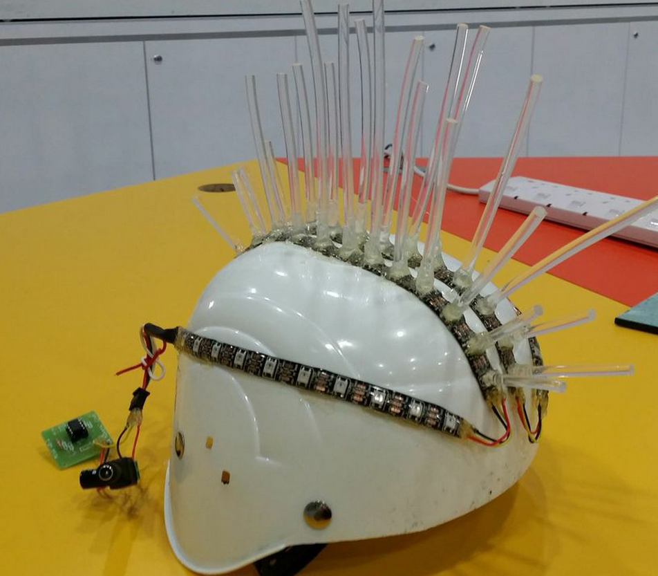
techno mohawk, maker faire, arduino, ATtiny85, WS2812 RGB LED


yours truly has devised this Q&D contraption for singapore mini maker faire #SMMF2014

Check this previous post on how to use Arduino, ATtiny85, WS2812/2811 RGB LED strip http://shin-ajaran.blogspot.sg/2014/04/wearable-electronics-arduino-x-attiny85.html

The contraption below use almost similar components, except the fiber optic 5mm strands as mohawk.

Wiring of this contraption is as per the following diagram.


The following diagram describe the crafting of this contraption.


video here


code here

Friday, July 4, 2014

3D printing with wood filament

3D printing with wood filament
This week the wood filament by laywood is explored for 3D printing using makerbot replicator2. 3D printing in wood offers a new range of application.  Experimentation with this new medium to explore the possibilities of what can it used for. The beauty of this wood filament, it can be post treated as per the usual wood working, sanding included.
Loading of the wood filament into makerbot replicator2 for 3D printing is a breeze. Check out the previous post of modifying the loading mechanism http://shin-ajaran.blogspot.sg/2014/04/3d-printing-using-ninjaflex-with.html
Standard PLA setting from makerware is used, but the temperature is set to 180degC instead of the usual 210degC to explore the texture and colour of the 3D printed parts. “Oozing” is observed from the 3D printed parts. Oozing in this context refers to the web of fine threads hanging from wall to wall of the model akin to a spider web. It has a term for it: “oozing while printing”.
Further refinement of the speed of filament extrusion/retraction, speed while extruding, and speed while travelling need to be tweaked to achieved a “cleaner” 3D printed parts.
A challenging model to print without support, due to the overhangs that are spiralling up.

This is the final output is plague with “oozing while printing”. Mentioned earlier, tweaking of the movement speeds of the 3 parameters are still waiting to be tweaked to perfection.

This website http://reprage.com/post/37966750340/how-do-i-stop-plastic-from-oozing-when-3d-printing/ offers some suggestions such as lowering the temperature of the hot end, reducing the movement speed, and increasing the retraction length. All the above requires time to discover the best settings!