Showing posts with label hardware. Show all posts

Saturday, March 1, 2014

Fujitsu E8410 laptop LCD panel LT154P3-L02 with LCD controller A.VST29.01

Fujitsu E8410 laptop LCD panel LT154P3-L02 with LCD controller A.VST29.01
Couple of weeks back I gave my well-deserved Fujitsu E8410 laptop a break, with it broken down into parts level. The LCD controller A.VST29.01 I ordered arrived early last week. It is Chinese made, and I can even find a data sheet for it on the Internet. With proper documentations, gone are the days we have to make some educated guesswork on unknown PCB. The price is USD29.9 without the AC adapter (12V, 4A); USD 51 for the complete set.
My schedule is still as hectic as hell, at the office and during office hours I am distracted with human presence, spent most of the time solving other human’s problem. Only at the weekends in the dead silence of my office, I am highly productive. In this precious undisturbed time I get things done.
In the comment post some ask why I would take all the trouble to fix instead of buying new laptop. 99% time these are the trolls that are trying to promote their business on blogs that allow for comment.  My answer: Re-purposing old electronics will reduce human’s dependency on Mother Nature’s generosity. 
The boom in electronics driven by capitalistic consumerism has humans scrambling to mine lithium to be used in rechargeable batteries, fossil fuels, precious metals to be used in producing electronics circuit boards and more. It is just a matter of when natural resources will be depleted, and I am dead sure I will not survive to see discarded electronics in the landfill takes it natural cause to be turned into resources again. Prolonging the EOL of electronic products by repurposing into other usage should reduce electronic waste. Some might argue that using another piece of electronics to prolong EOL (End Of Life) is also capitalistic consumerism and driving consumption. True, but to a certain extend. I do not have the exact quantitative data to retort this rhetorical statement. Nonetheless, qualitatively, if 100 units of resources are used to manufacture a laptop and deliver it to end user, contrasting it with 10 units of resources are used to manufacture an electronic circuit and delivered to end user to prolong it; the projected 90 units of unconsumed resources would stay unmolested in the sacred earth reserves.
Major manufacturing house would love to silence disapproving voices like mine that might hurt their profit base line by not consuming/buying new stuff. The power is to the people with a choice, liberated with domain knowledge shared by inhabitants on the Internet. We are not alone.
Let the transmission of how-to begin.
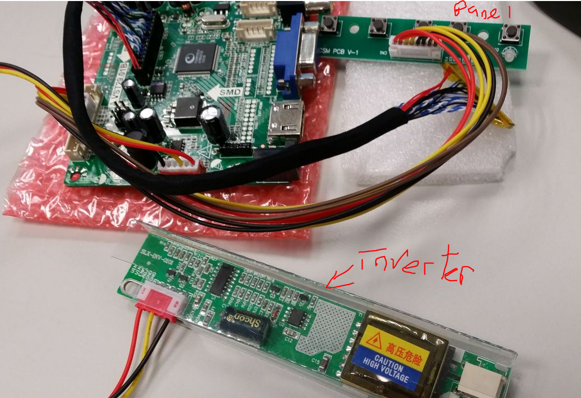
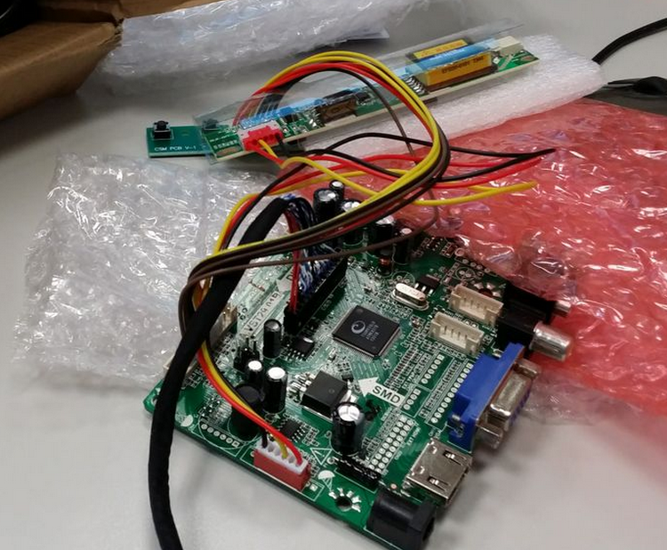
The package comes in 3 PCBs. The largest piece is the LCD controller, the larger rectangle shape PCB is the Inverter, it’s purpose is to power up the LCD panel’s backlight. Warning: the inverter contains high voltage during operation. Even it is disconnected from the supply, ensue safety precautions such as disconnecting from the mains, wear rubber sole shoes, not touching any bare metal area (soldering on the PCB are exposed to touch) are taken before handling the inverter PCB. There is a clear plastic surrounding the inverter. That is not meant for decoration, but prevents accidental in contact with the exposed area. DO NOT REMOVE THIS PLASTIC COVER! The smaller rectangle PCB is the panel where there are push button switches to control OSM (On Screen Menu).
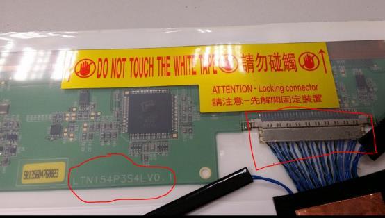
The how-to is simple. Merely dismantle the LCD panel to the bare component level, remove the original LVDS cable and replace it with the one that comes with the LCD Controller. Some are weary of carelessness of flipping the connector and make a blunder out of it. No fret! The LVDS connector only goes in one direction, due to the design of it as depicted in the picture below from the LCD controller. Well, forcing the reversed connector definitely will damage the LCD panel and LVDS connector. The LVDS connector is replaceable, but not the receiving side on the LCD panel.
The following diagrams depict the original cable in 3 states. “A” is written to depict the direction and also the orientation of the connector. Just my handy way of labelling things I am opening up for the first time and ensuring I can put it back as per the original state later.
After assembling the LVDS cable, this is how it is look like.
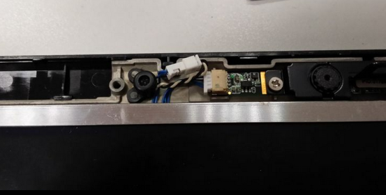
The bird-eyes view of the connection.
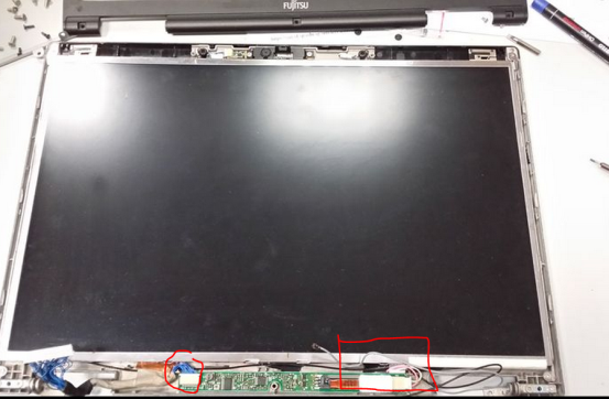
Circle in red is where the LCD panel’s back lamp is connected to the inverter. Square in red is the LCD controller’s LVDS cable connecting to the LCD panel. Some scotch tape is used to secure the wiring at a convenient location.
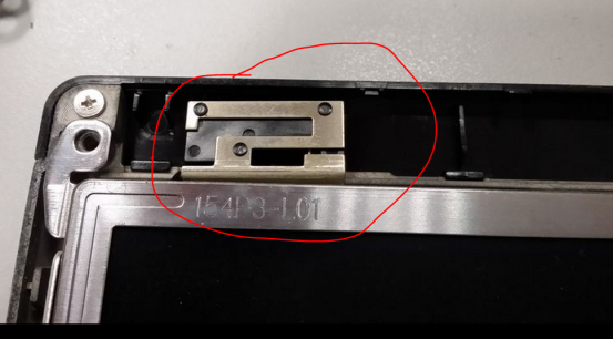
The E8410 laptop boasts a magnesium alloy casing on the LCD (that’s the reason I choose the model!!), and it is difficult to cut through metal with my bare minimal tools. So I have made an inconspicuous  incision at the plastic area of the front cover to allow wiring to pass.
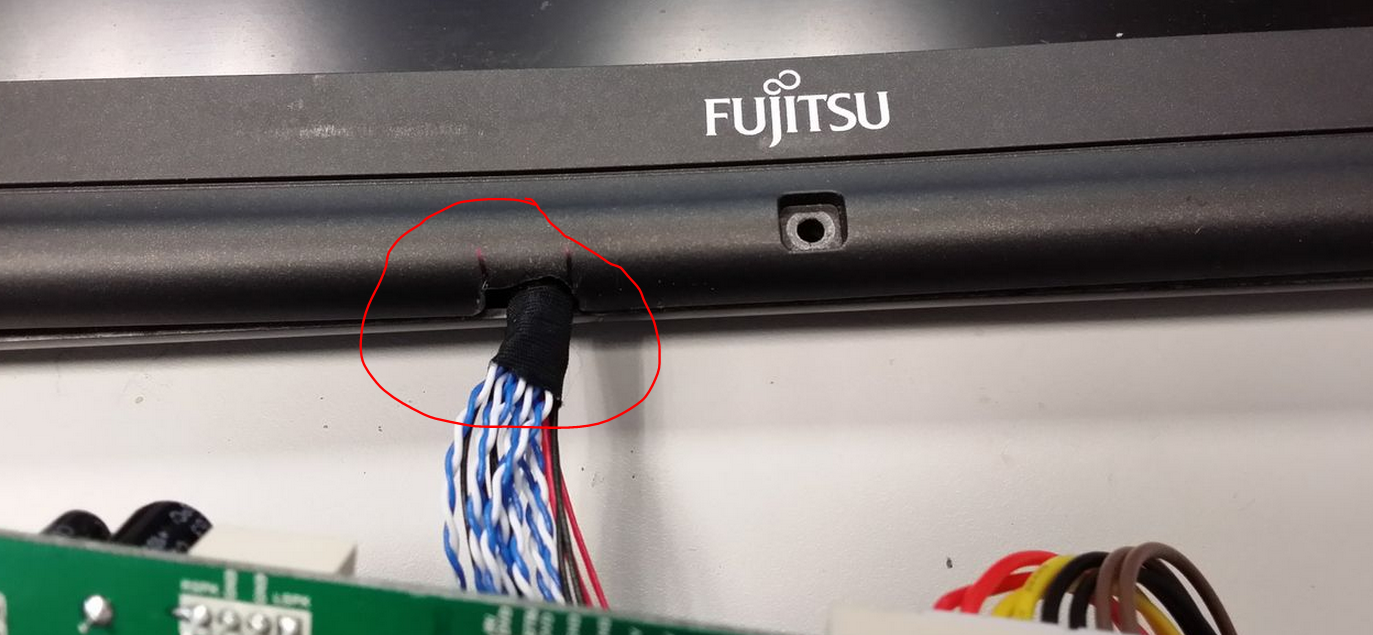
A final check before turning it on! This step is very crucial! Do not skip the final check before turning on!!!
Turning it on, and familiarising with the OSM.
Connecting it to the vga of my gaming rig (i7, 8GB ram, 128GB SSD, GTX 550Ti, win7x64), it works at 1280x720. One short note, I connected it to the VGA of my office laptop (i7, 500GB,8GB ram, win7x32{I know, this is a piece of joke. Stop making fun of it}) prior to my gaming rig. I have tried a myriad of resolution from 640x480 to 1280x720. Unfortunately, office laptop decides not to co-operate. Luckily I have my gaming rig in my office to offer a second opinion. Otherwise, I would have to hastily conclude my weekend project in my office a failure. Oh, did I mention that my gaming rig is in my office???!!

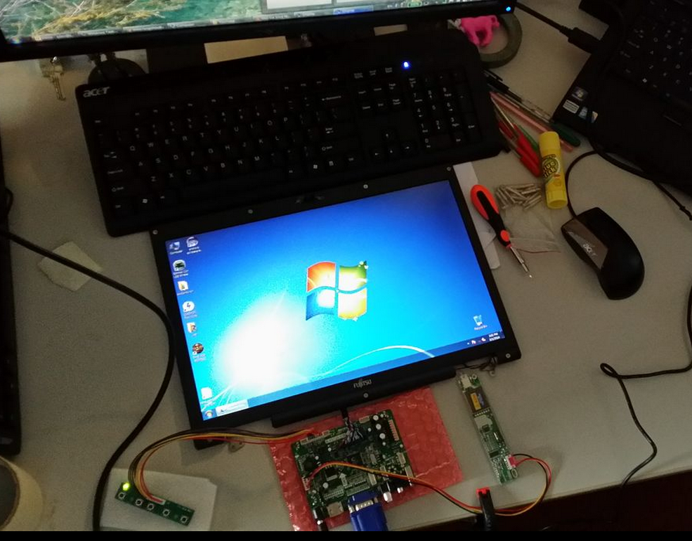
This weekend is the IT show in Singapore and I am such a cheapskate to spent very little $$. LOLx

Monday, February 3, 2014

Breaking down a laptop for tasty spare parts

Breaking down an E8410 laptop for tasty spare parts

What better to do on an off day in-lieu and long weekend for the Lunar New Year??? Doing my back log/computer stuff of course!!

Some years back in late 2007 I bought my full specs laptop, the
Fujitsu E8410. By full spec, it is one of the heaviest contenders in the heavy weight category. This truly sturdy work horse of mine survived many of my computing abuses, stressed under tremendous computing intensive loads (read: playing game that demands lots of CPU at ultra high graphics).  E8410 survived logically. Physically, E8410 was put under extreme body alteration one such is modifying with 500GB worth of HDD . Due to BSOD and core dump in Feb2012 E8410 was put in the reflow oven to reball the onboard graphics card Balls Grid Array (BGA) connector. It worked for about 4 months or so, until it took an arrow in the knee and sent for the reflow oven again. It went unloved since then, as I got myself a Dell XPS14, and we eloped to London.  Silently, like a lover that truly loves me first, E8410 faded in the background, hiding in a dark corner. E8410 throws tantrum too.... this was in 2007 https://www.dropbox.com/s/lepe4opbopn1tye/vga%20screwed%202.bmp

It is not coincidence for me to recall the excitement with this old horse of mine. So, I pulled it out from the bottom of the abyss, and blew it with a kiss. But E8410 reciprocated with 1 long beeps and 3 short beeps; the beeps of a missing graphic card.
E8410 might be gone, but the legacy remains. Who doesn’t want an extra 8GB worth of DDR2 667 rams, 500GB of HDD, dvd writer, and the crown of all spare parts: the ultra responsive 15.4” WXGA LCD screen. The parts come in handy; reviving dead laptops, and continuing the legacy where the stories of E8410 continue.
WARNING: GRAPHIC CONTENT AHEAD. Breaking down of a laptop
Remove all visible screws from the bottom plate.
Rams and HDD are extracted first.
Under the hood.
500GB HDD and 8GB worth of RAMs.
Circle in red is a screw that is hidden beneath a piece of stopper. Crucial step is to uncover all of these hidden screws prior to dismemberment.
Circle in red is one of the many hidden screws that secures to the hinge of the LCD. Proceed with care.
Carefully pry/lift the diagnostic LCD face plate. Disconnect the ribbon cable circle in red.
Circle in red is the proprietary connector to the LCD+microphone+camera. the top plate an be used as an in situ replacement for similar laptop with damaged screen, thus extra effort needed for not damaging the connector. Triangle in red is the hinge of the LCD panel. Box in red is the WiFi PCI-E mini, note the 3 little connectors on the RHS to plug in the pigtail (wire to an antenna). WiFi card comes in handy in the absence of USB WiFi.
Size of pin compared relatively to a screw driver
Oh, did I mention that my work horse was enhanced with 2x WiFi adapter?! Only those that needed it will know the convenience of embedding an extra hardware.
Ahhhhh, the crown piece, savour the moment.
Laptop facing up, carefully lift up the keyboard from the side groves. The keyboard is snapped together by plastic hinges to the bottom plate. Red box is the connector for keyboard, red circle is the connector for mouse pad. Take extra precaution not damaging the connector. The keyboard and mouse will come in handy
.
Circle in red is metal piece that is connected to the LCD panel’s antenna.  
Carefully lift the plastic plate that consist of the speakers and mouse pad from the side groves. You have come that far of lifting the hood. Observe a moment of silence please….
An insert and latch type connector that is used by the mouse.
Fancy some stereo miniaturized speakers?
Unscrew, lift up and then disconnect to save the WiFi cards for later use.
Remove the copper pipe heat sink.
 Box in red is the T7300 C2D 2GHz CPU; circle in red is the NVidia graphic card that is giving me the problems. Too bad the graphic card is non-upgradable.
Protect the CPU pins with foam or better an ex cpu tray holder. Any bent pins on the CPU will render it useless and defeat all the efforts put in to break down the laptop.
Breaking down the LCD panel of a Laptop
The following steps are optional. I am breaking down the LCD panel for the same of finding the part number. I have a plan to revive the legacy, by making the E8410 15.4” laptop LCD panel as a TV, secondary monitor or even a photo frame (ok, this might be an overkill for the time, $$, and effort).
circle in red are the hidden screws on the LCD panel itself.
Take upmost care when removing the front plastic panel. Aesthetics is the must for a repurposed LCD panel. It will be such an eye sore staring at an asymmetrical, dented or chipped LCD panel. Circle in red is the proprietary connector to the microphone and camera. Notice it is much smaller than the one connected to the mother board showed earlier. Box in red is the connector is form the inverter to the backlight of an LCD. Most unloved LCD monitors have a malfunctioned inverter/backlight. If you saw one BIG A$$ LCD at the rubbish bin, pick it up quickly and hurry to your techno lair to assess the situation. Replacing the backlight/inverter is a fraction cost of the LCD monitor your just picked up!
closeup
microphone and camera can be repurposed too. Making the camera to work as a USB webcam is a challenge to boot!
circle in red is the antenna for WiFi adapter
Carefully lift up the LCD screen and backlight from the bottom cover. DO NOT attempt to touch the electronics covered by the transparent insulation. Working on power electronics without proper rubber sole shoes risks electrocution. Now the moment of truth, Circle in red is the LCD panel part number. It will come in handy while looking for a LCD panel driver from friendly internet sources. Box in red is the LCD panel’s data connector. This connector must be preserved at all cost, otherwise, it cannot be repurposed as a standalone LCD monitor.
Guess the manufacturer of this LCD panel?
Now, the making of a standalone LCD monitor by repurposing a laptop’s LCD screen is worthy of a post by itself. Akan Datang…………….
If you wonder how I keep the screws.


Tuesday, October 14, 2008

[CHW] Intro to PC INNARDS

Having being introduced to the inner working world of a computer, do you dare to take a peek "under the hood" of your own computer?
What are the reasons that are holding you back to "open up" your own computer???
What are the precautions you would take?

Long time ago....
when I was a kid, I got my first computer, it was an "IBM clone" Pentium 100Mhz, 16MB EDO ram, VERY PATHETIC HDD, 2x CDrom. I still remember vividly, it cost my dad's 1 month worth of pay! The day I got it, I open it up.
No guru teach me, no people guide me, I just have the "thing" to open it up.

To make sure I am able to "put it back together", not missing a screw and such I use marker pen to draw a line between the connecting "joints".

Something that I observed and questions that arised...

1. What are the red lines doing at that "flat looking cable" (that time did not know it was called [TTDNKIWC] IDE cable) always connected to the "pin looking thing" (TTDNKIWC) at pin 1?

2. The connectors only have 1 direction of plugging in. Is it possible to plug it the other way round?

3. Do all the computer look the same "under the hood"?

4. the black ports (ISA slots) got a sound card, the white ports (PCI slots) got a graphic card.

5. etc...............................................

share your discoveries...........................