Breaking down an E8410 laptop for tasty spare parts
What better to do on an off day in-lieu and long weekend for the Lunar New Year??? Doing my back log/computer stuff of course!!
Some years back in late 2007 I bought my full specs laptop, the Fujitsu E8410. By full spec, it is one of the heaviest contenders in the heavy weight category. This truly sturdy work horse of mine survived many of my computing abuses, stressed under tremendous computing intensive loads (read: playing game that demands lots of CPU at ultra high graphics). E8410 survived logically. Physically, E8410 was put under extreme body alteration one such is modifying with 500GB worth of HDD . Due to BSOD and core dump in Feb2012 E8410 was put in the reflow oven to reball the onboard graphics card Balls Grid Array (BGA) connector. It worked for about 4 months or so, until it took an arrow in the knee and sent for the reflow oven again. It went unloved since then, as I got myself a Dell XPS14, and we eloped to London. Silently, like a lover that truly loves me first, E8410 faded in the background, hiding in a dark corner. E8410 throws tantrum too.... this was in 2007 https://www.dropbox.com/s/lepe4opbopn1tye/vga%20screwed%202.bmp
It is not coincidence for me to recall the excitement with this old horse of mine. So, I pulled it out from the bottom of the abyss, and blew it with a kiss. But E8410 reciprocated with 1 long beeps and 3 short beeps; the beeps of a missing graphic card.
E8410 might be gone, but the legacy remains. Who doesn’t want an extra 8GB worth of DDR2 667 rams, 500GB of HDD, dvd writer, and the crown of all spare parts: the ultra responsive 15.4” WXGA LCD screen. The parts come in handy; reviving dead laptops, and continuing the legacy where the stories of E8410 continue.
WARNING: GRAPHIC CONTENT AHEAD. Breaking down of a laptop
Remove all visible screws from the bottom plate.
Rams and HDD are extracted first.
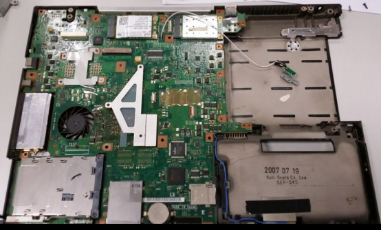
Under the hood.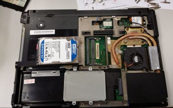
500GB HDD and 8GB worth of RAMs.
Circle in red is a screw that is hidden beneath a piece of stopper. Crucial step is to uncover all of these hidden screws prior to dismemberment.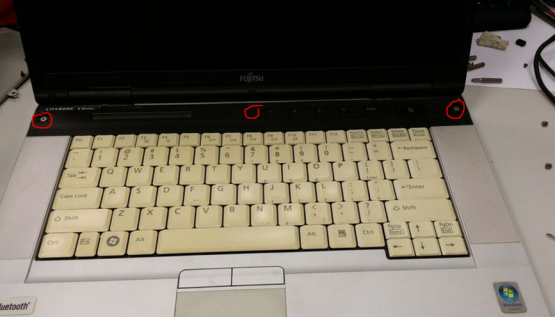

Circle in red is one of the many hidden screws that secures to the hinge of the LCD. Proceed with care.
Carefully pry/lift the diagnostic LCD face plate. Disconnect the ribbon cable circle in red.
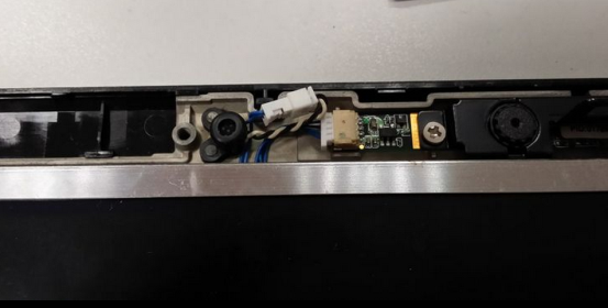
Circle in red is the proprietary connector to the LCD+microphone+camera. the top plate an be used as an in situ replacement for similar laptop with damaged screen, thus extra effort needed for not damaging the connector. Triangle in red is the hinge of the LCD panel. Box in red is the WiFi PCI-E mini, note the 3 little connectors on the RHS to plug in the pigtail (wire to an antenna). WiFi card comes in handy in the absence of USB WiFi.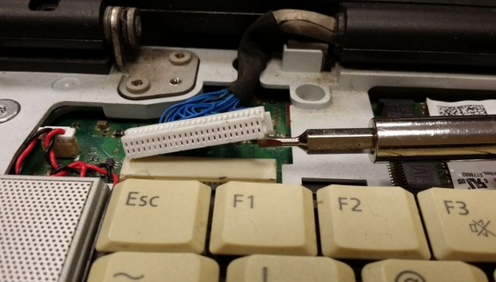
Size of pin compared relatively to a screw driver
Oh, did I mention that my work horse was enhanced with 2x WiFi adapter?! Only those that needed it will know the convenience of embedding an extra hardware.
Ahhhhh, the crown piece, savour the moment.
Laptop facing up, carefully lift up the keyboard from the side groves. The keyboard is snapped together by plastic hinges to the bottom plate. Red box is the connector for keyboard, red circle is the connector for mouse pad. Take extra precaution not damaging the connector. The keyboard and mouse will come in handy
.
.
Circle in red is metal piece that is connected to the LCD panel’s antenna.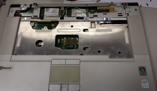
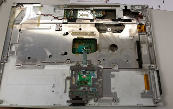
Carefully lift the plastic plate that consist of the speakers and mouse pad from the side groves. You have come that far of lifting the hood. Observe a moment of silence please….
An insert and latch type connector that is used by the mouse.
Fancy some stereo miniaturized speakers?
Unscrew, lift up and then disconnect to save the WiFi cards for later use.
Remove the copper pipe heat sink.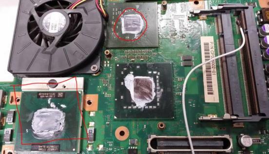
Box in red is the T7300 C2D 2GHz CPU; circle in red is the NVidia graphic card that is giving me the problems. Too bad the graphic card is non-upgradable.
Protect the CPU pins with foam or better an ex cpu tray holder. Any bent pins on the CPU will render it useless and defeat all the efforts put in to break down the laptop.
Breaking down the LCD panel of a Laptop
The following steps are optional. I am breaking down the LCD panel for the same of finding the part number. I have a plan to revive the legacy, by making the E8410 15.4” laptop LCD panel as a TV, secondary monitor or even a photo frame (ok, this might be an overkill for the time, $$, and effort).
circle in red are the hidden screws on the LCD panel itself.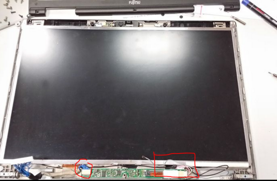
Take upmost care when removing the front plastic panel. Aesthetics is the must for a repurposed LCD panel. It will be such an eye sore staring at an asymmetrical, dented or chipped LCD panel. Circle in red is the proprietary connector to the microphone and camera. Notice it is much smaller than the one connected to the mother board showed earlier. Box in red is the connector is form the inverter to the backlight of an LCD. Most unloved LCD monitors have a malfunctioned inverter/backlight. If you saw one BIG A$$ LCD at the rubbish bin, pick it up quickly and hurry to your techno lair to assess the situation. Replacing the backlight/inverter is a fraction cost of the LCD monitor your just picked up!
closeup
 microphone and camera can be repurposed too. Making the camera to work as a USB webcam is a challenge to boot!
microphone and camera can be repurposed too. Making the camera to work as a USB webcam is a challenge to boot!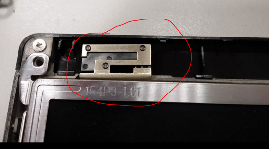
circle in red is the antenna for WiFi adapter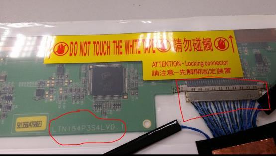
Carefully lift up the LCD screen and backlight from the bottom cover. DO NOT attempt to touch the electronics covered by the transparent insulation. Working on power electronics without proper rubber sole shoes risks electrocution. Now the moment of truth, Circle in red is the LCD panel part number. It will come in handy while looking for a LCD panel driver from friendly internet sources. Box in red is the LCD panel’s data connector. This connector must be preserved at all cost, otherwise, it cannot be repurposed as a standalone LCD monitor.
Guess the manufacturer of this LCD panel?
Now, the making of a standalone LCD monitor by repurposing a laptop’s LCD screen is worthy of a post by itself. Akan Datang…………….
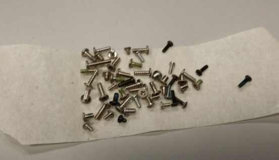
If you wonder how I keep the screws.


