Saturday, May 24, 2014

Operate 3D printing on reprap 3D printer with octoprint and slic3r

Operate 3D printing on reprap with octoprint and slic3r
Generically, 3D printing is a process to realise an object physically from a digital copy. The digital copy of an object, can be created using CAD tools such as autodesk inventor, 123D, tinkercad, Sketchup, Maya, Rhino3D, and many more. The 3D model to be 3D printed usually comes in *.STL, and it needs to be translated to a format where the 3D printer can understand: GCODE (for reprap based 3D printers), X3G (for makerbots). Regardless of the file extension, the 3D printer only understands instructions in the form of X , Y, Z axis movement, and amount of filament to extrude.
So, what is the GCODE consist of? The following is a snippet of GCODE
[CODE]
; generated by Slic3r 1.0.0 on 2014-05-20 at 21:07:43
; layer_height = 0.2
; perimeters = 3
; top_solid_layers = 3
; bottom_solid_layers = 3
; fill_density = 1
; perimeter_speed = 30
; infill_speed = 60
; travel_speed = 130
; nozzle_diameter = 0.35
; filament_diameter = 1.75
; extrusion_multiplier = 1
; perimeters extrusion width = 0.35mm
; infill extrusion width = 0.52mm
; solid infill extrusion width = 0.52mm
; top infill extrusion width = 0.52mm
; support material extrusion width = 0.35mm
; first layer extrusion width = 0.60mm
G21 ; set units to millimeters
M107
M190 S40 ; wait for bed temperature to be reached
M104 S175 ; set temperature
G28 ; home all axes
G1 Z5 F5000 ; lift nozzle
M109 S175 ; wait for temperature to be reached
G90 ; use absolute coordinates
G92 E0
M82 ; use absolute distances for extrusion
G1 F1800.000 E-10.00000
G1 Z0.400 F7800.000
G92 E0
G1 X58.780 Y66.400 F7800.000
G1 Z0.200 F7800.000
G1 E10.00000 F1800.000
G1 X59.740 Y65.610 E10.05427 F540.000
G1 X60.840 Y65.020 E10.10876
G1 X62.030 Y64.660 E10.16304
[/CODE]
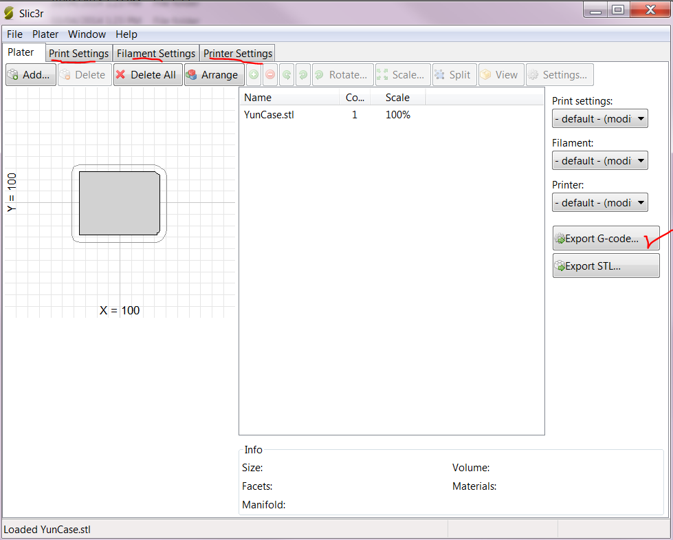
To create GCODE from STL file, one of the available software is Slic3r http://www.slicer.org/ an open source software. The generic steps to generate GCODE using Slic3r is as follow
  1. Setup Slic3r on local computer
  2. Setup configs for 3D printer on Slic3r. I reckon 3D printers suffer from individualism, each of them requires some form of tuning or calibration to achieve the best effect. I have uploaded the configs to my 3D printer here. Just got to file-> load configs
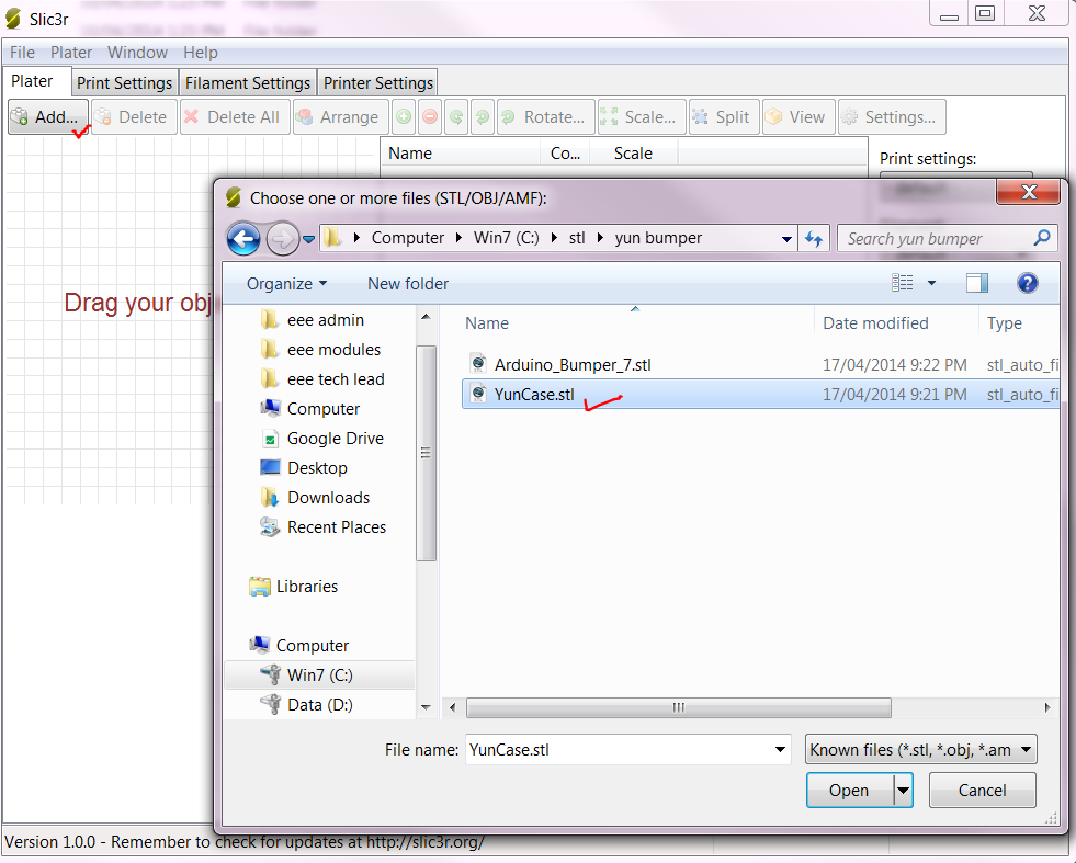
    Note: Step 1 & 2 need to be done once only.
  3. Select an *.STL by clicking on the “Add” button
    Note: the model in the *STL needs to be position on the platform, otherwise, need to manually position in Slic3r.
  4. There is a default mode in Slic3r, presumably works on most 3D printer. Press on the button “Generate GCODE” to complete this process. For the sake of simplicity, the tabs on Print, Filament, Printer settings can be save/load as config to save the grace

  5. There will be a popup box asking for the directory to save the GCODE. Observe the path to the directory and click “OK” to complete.
The following steps describe the process of 3D printing using Octoprint with a pre-existing GCODE file.

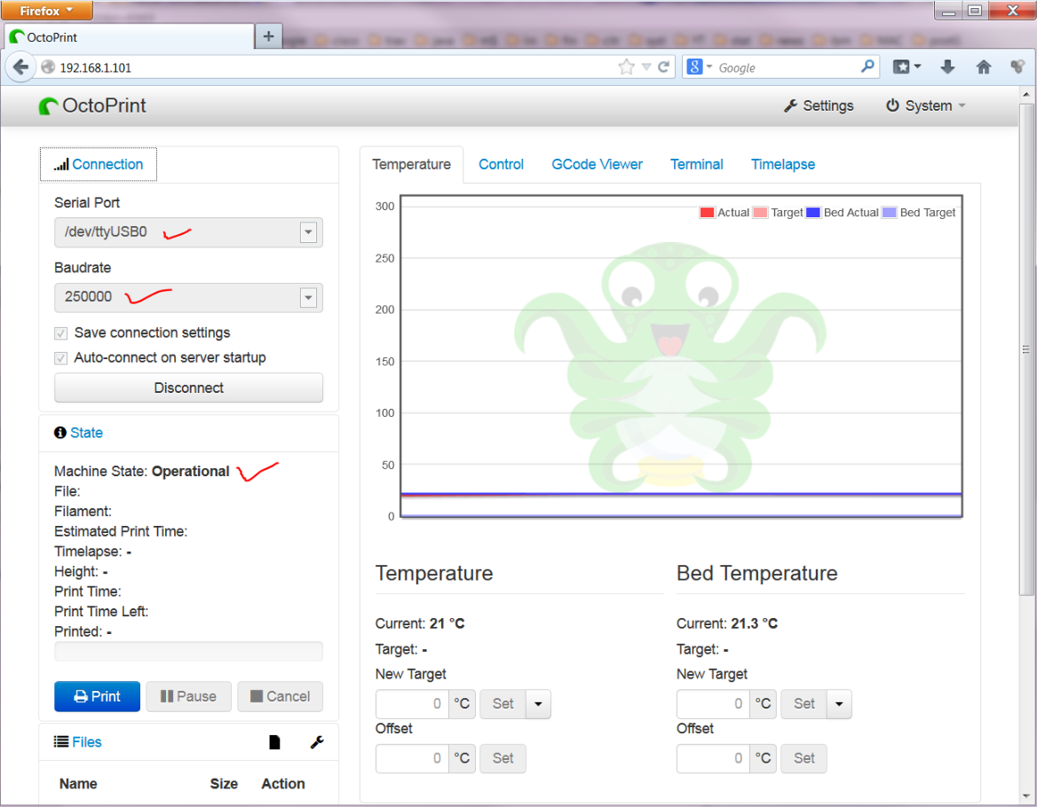
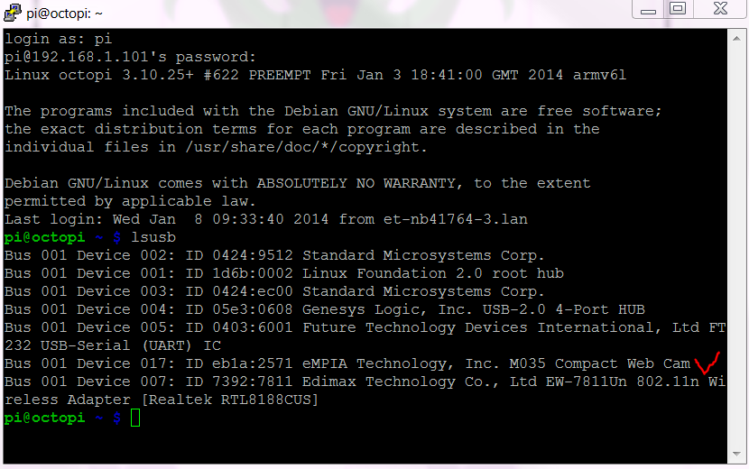
  1. With a browser such as Firefox or Safari, browse to the ip address of the octoprint. If this is the first time connecting, the serial port and baudrate need to be set. Otherwise, it will automatically connect.
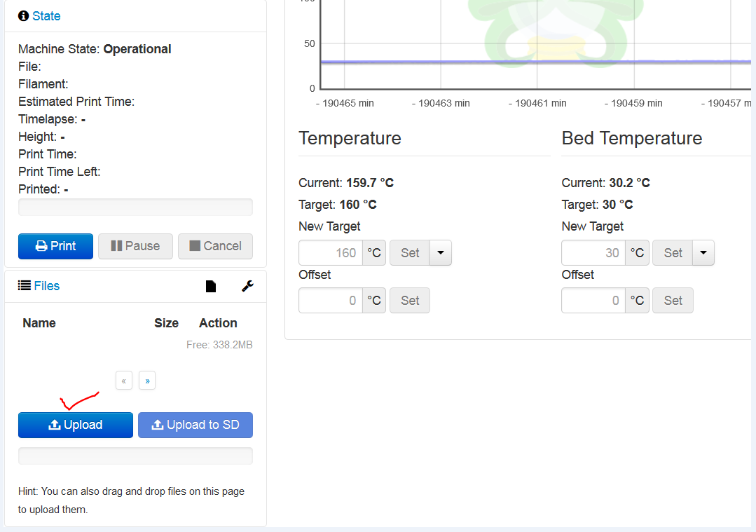
  2. Locate the upload button on the lower RHS of the GUI, and press upload.
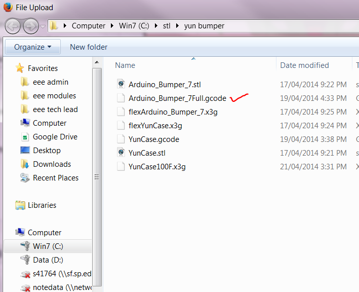
  3. Select the corresponding *.GCODE to be printed and then click “OK” to confirm. Wait for the upload to complete.
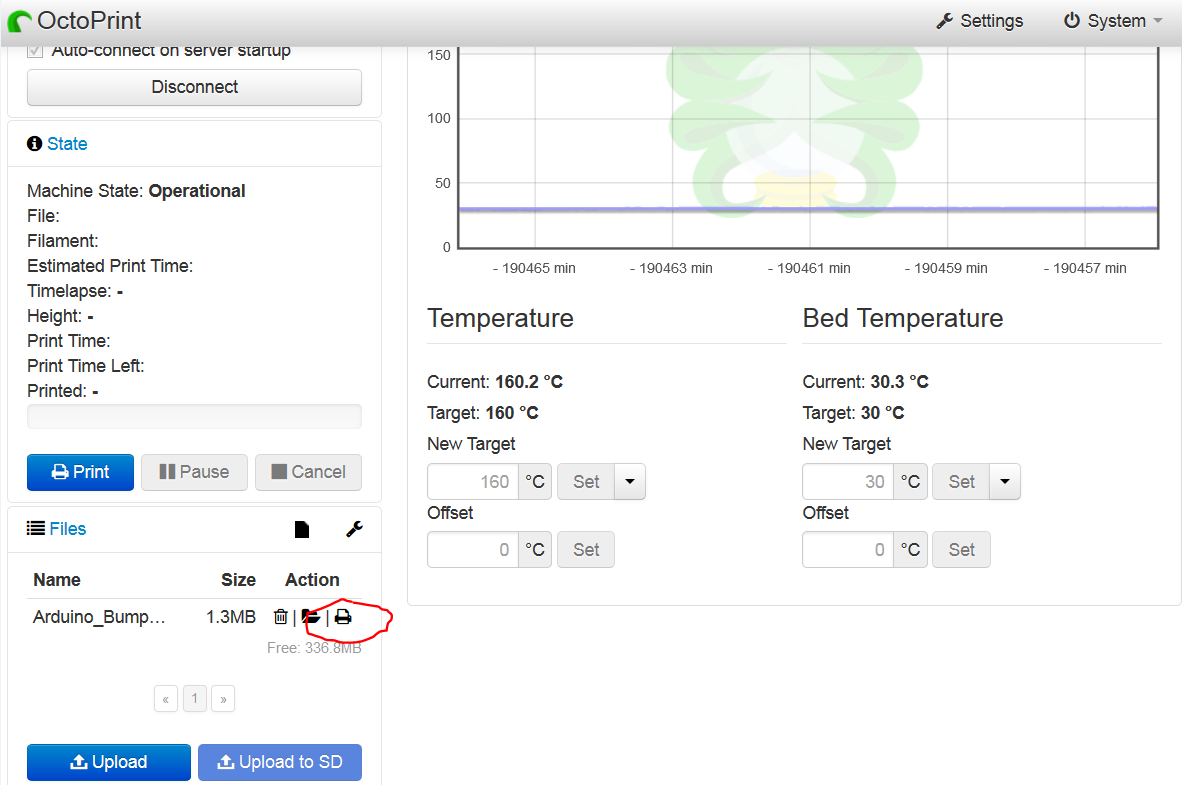
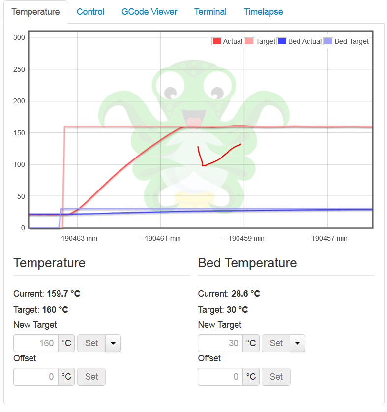
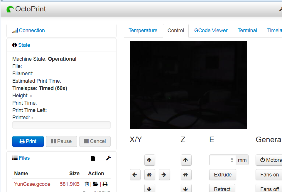
  4. Locate the printer button next to the file uploaded and click on it. This will initiate the printing. Once the extruder and heated bed temperature reached the desire temperature, printing will starts by itself.
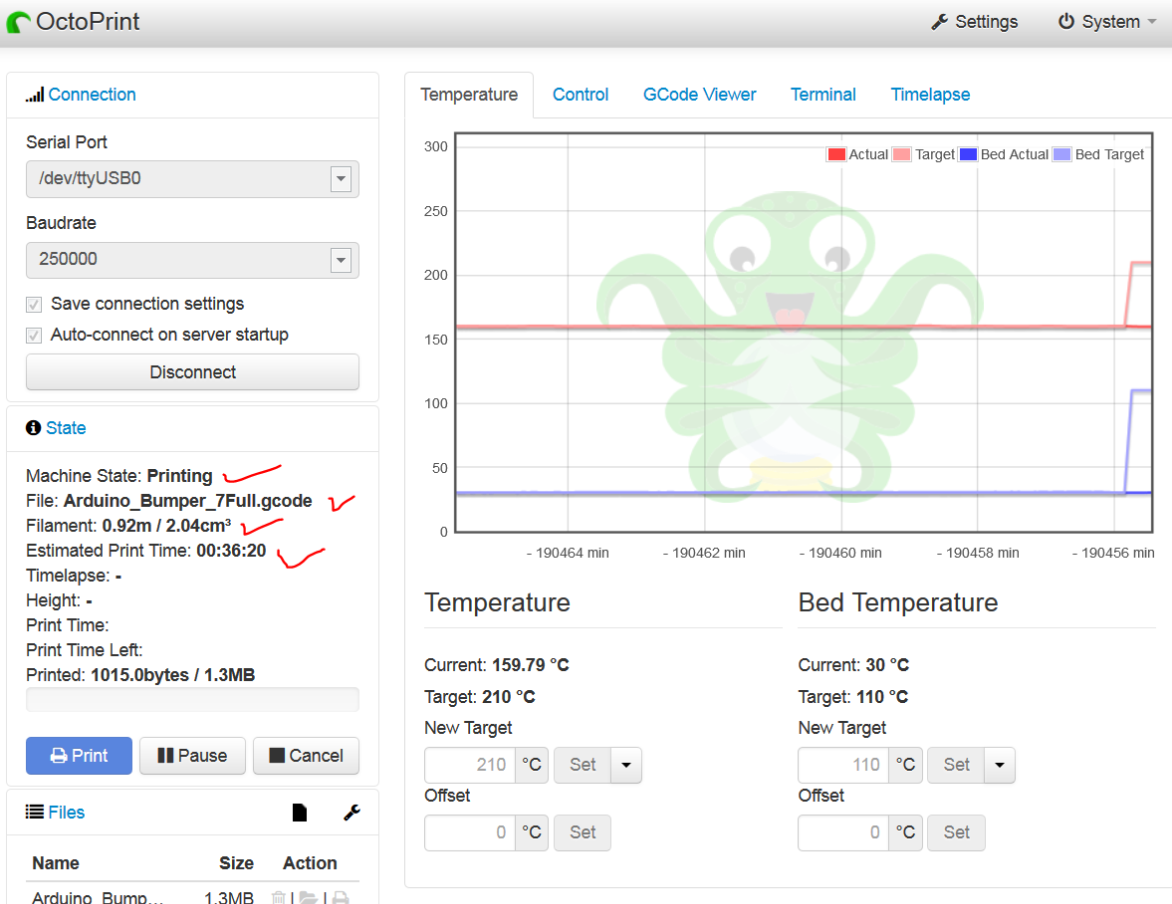
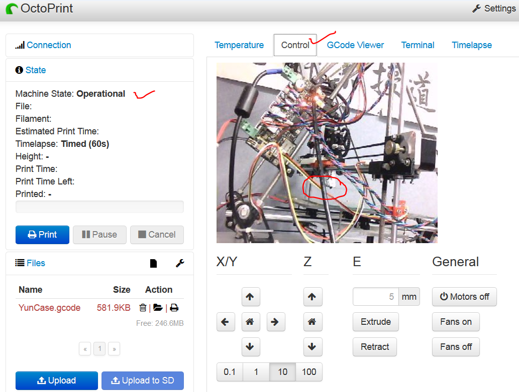
  5. Printing related diagnostic data such as time, material and progress can be observed on the LHS
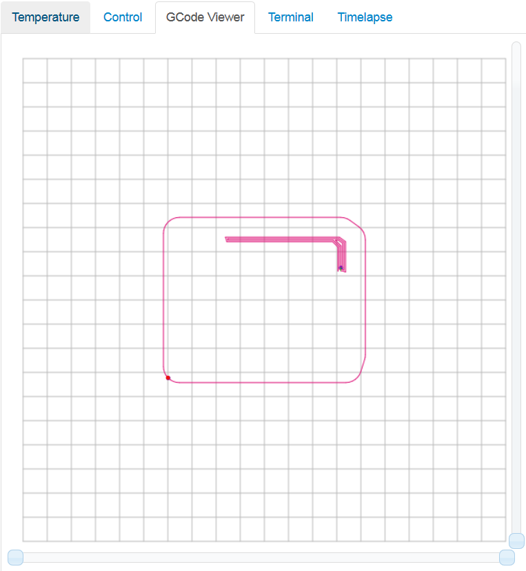
  6. Clicking on the GCODE viewer tab will yield the visualization of the current line of instruction in GCODE
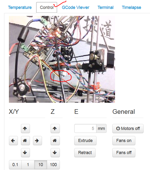
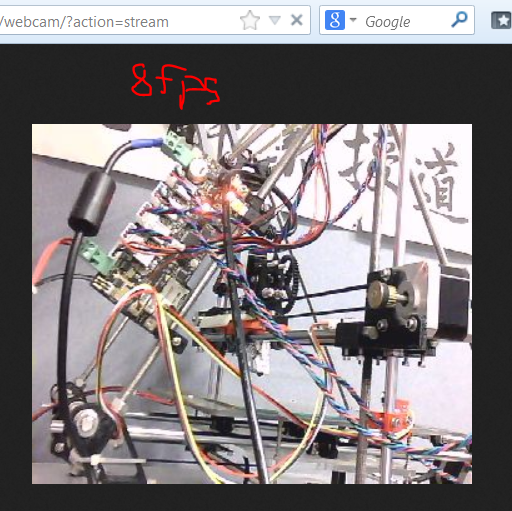
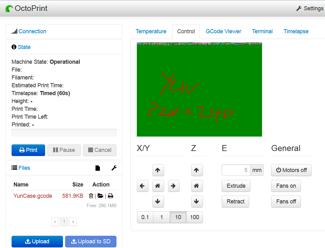
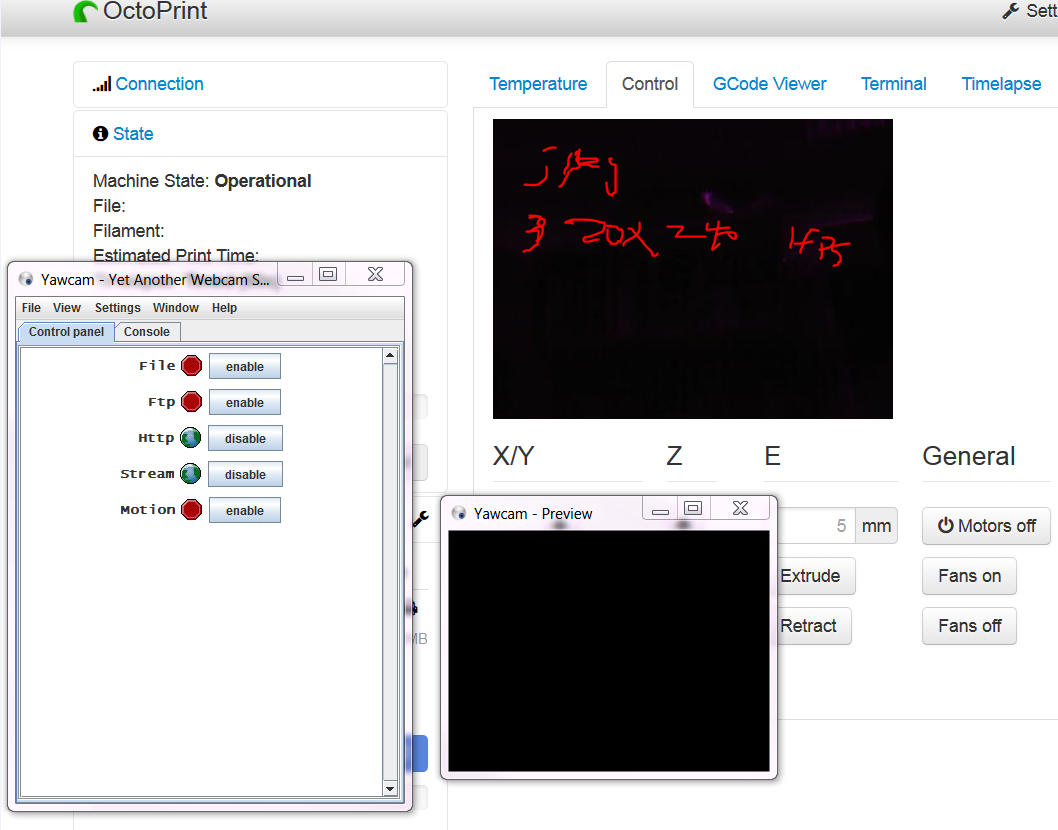
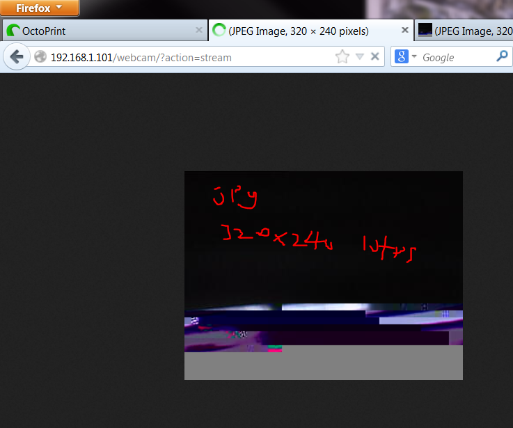
  7. Clicking on the controls tab will yield the streaming of the 3D printing process
  8. All needed now is time for the 3D printing to complete.

Cloudify: setup reprap 3D printer with octoprint, mjpg_streamer on raspberry pi

Cloudify: setup reprap 3D printer with octoprint, mjpg_streamer on raspberry pi
The process to 3D print a 3D model can be quite an obstacle, i.e need to have physical access to the 3D printer and a SD card handy, power hog, heat emission, UFP emission. What if we can remotely send a 3D model (in *.STL) to be 3D printed on a 3D printer and also observe the 3D printing process over the Internet? Definitely it is going to be convenient as everything can be done at the fingertips; godsend piece of technology for those can’t wait for the 3D printers to be locked down in a facility equipped with exhaust and medical grade filter that is capable of filtering Ultra Fine Particles (UFP) in the range of 100 nanomether that is much finer than PM2.5. The purpose of this article is to share a step by step guide of setting up 3D printer to print remotely.
Raspberry Pi is acting as the “brain”, wirelessly receiving GCODE (instructions for the 3D printer to work by processing a 3D model file in STL using software such as Slic3r http://slic3r.org/ ) from the front end that is interfacing between human and 3D printer via OctoPrint http://octoprint.org/ providing minute control over the 3D printer; feedback to human by streaming 3D printing process via MJPG_streamer http://sourceforge.net/projects/mjpg-streamer/ . Most 3D printers in the market have only 1 MCU, e.g 1 brain. Usually 3D printing is done by inserting a SD card that contains the GCODE and to be read by the 3D printer. Having a second brain opens up more opportunity to build computing capacity for the 3D printer. Cloudify, refers to scaling up this computing methodology to support more users and more 3D printers.
A quick note: Raspberry Pi is sensitive to power drop, especially when there are a few components drawing substantial amount of power to operate. One of the tell-tale sign is when a keyboard is plugged in to console the raspberry pi, the keystrokes appear to be non-responsive.
Another not so quick note: Throughout this process of setting up, yours truly learnt that apparently not all USB webcamera out there work out of the box on the raspberry pi. The details steps of configuring and observations done are recorded at the end of this article.
Parts needed
  1. RepRap 3D printer or equivalent, known baud rate of the 3D printer e.g 250000
  2. Powered USB hub, preferably 5V 1A; (tested with Belkin F4U020)
  3. USB webcam (tested both Creative VF0220; A1 pro M035 ); list of tested USB webcam on raspberry pi is here http://elinux.org/RPi_USB_Webcams
  4. Raspberry Pi as the controller/brain;
  5. WiFi adapter;
  6. WiFi Access Point; IFF necessary
Steps required
  1. If there is an existing pi setup and reflash the SD card image is not an option, build octoprint on your raspberry pi https://github.com/foosel/OctoPrint/wiki/Setup-on-a-Raspberry-Pi-running-Raspbian. Alternatively, download octopi image https://github.com/guysoft/OctoPi; it is a custom fit raspbian with the goodies such as octoprint, mjpg_streamer, and more!
  2. Setup WiFi access for the raspberry pi. Depending on the WiFi network connected to, the wpa_supplicant.conf will vary. Here are 2 examples of configuration http://shin-ajaran.blogspot.sg/2013/06/raspberry-pi-connecting-to-wifi-in-ucl.html ; http://shin-ajaran.blogspot.sg/2013/06/a-poor-lads-guide-to-install-raspberry.html
  3. Wire the parts according to the following picture that describes the wiring connection
 
  1. Turn on the powered USB hub, the reprap3D printer, the WiFi Access Point (If used)
  2. Console in via SSH using Putty or equivalent;
  3. Issue the command “lsusb” to verify the devices are mounted accordingly to raspberry pi
  4. Navigate to the ip-address using firefox or safari and be presented with the GUI of OctoPrint. On the upper LHS select the appropriate interface where reprap3D printer is connected e.g ttyUSB0 and the corresponding baud rate e.g 250000. Failure in doing so, the reprap 3D printer will not be interfaced. The following diagram describes the reprap 3D printer that is connected to octoprint

  5. Determine the control between the OctoPrint and reprap 3D printer by setting the temperature and observe the temperature over time. The following diagram describes the temperature recorded over time
  6. Click on the control tab. If the webcamera work out of the box, there should be a live feed in this tab as describe in the following picture. Otherwise, refer to the appendix on configuring USB webcams/troubleshooting
  7. Streaming of the 3D printing process can be observed from a browser pointing to http://IP-address/webcam/?action=stream
    D:\eee tech lead\octoprint reprap\wa3.PNG
  8. The GCODE viewer tab is a visualization of GCODE used in progress. The following diagram depicts the progress of printing an Arduino Yun Bumper. The step by step guide to 3D print with this computing methodology is available here
Appendix: troubleshooting the webcam for streaming
Finding the right USB webcamera (model/make), the right picture format (JPEG;YUY2), the right resolution (640x320, etc), and the right frame per second (fps) for mjpg_streamer on Raspberry pi is a tedious process. Getting the usb webcam to work is a little bit trickier than expected. Having a usb webcam that is not listed on the supported webcam on raspberry pi doesn’t help either. So yours truly is left on his own to conduct a few rounds of A/B tests.
The location to configure the webcam daemon that uses mjpg_streamer included in octopi is available at “ /home/pi/scripts/” the parameters associated with the webcam can be modified in the script “webcamDaemon” available in that directory. After completing the changes, save the file and execute the script. If this screen is encountered, a reboot of the raspberry pi is required.
The following describes the parameters used to determine the best output with Creative VF0220
##VF0220
#YUY2 320x240 @10fps = green
#YUY2 320x240 @25fps = green, hang after a while
#JPEG 320x240 @10fps = varying colour according to light. hang after awhile;cannot boot complete
#JPEG 320x240 @15fps = partial works with varying colour
#JPEG 320x240 @25fps=same as above with more frames of lights
#JPEG 320x240 @1fps = cant open cam; cannot boot complete;hang.
#JPEG 640x480 @15fps = varying colour then hangs very fast
#JPEG 640x480 @1fps = varying colour then hangs afte a while; then throw 503
#JPEG 352x288 @8fps= throws 503
#YUY2 352x288 @8fps= throws 503
This is the best can be achieved with VF0220


Courtesy of TSO Mark, yours truly get to use an USB webcam that is marketed locally as A1 pro, but recognised as M035 on raspberry pi.

The following observations are recorded
##M035
#JPEG 352x288 @15fps = no disp
#YUY2 352x288 @15fps = ok; hang if move camera too often.
#YUY2 352x288 @8fps= ok; no hang

Saturday, May 3, 2014

Laser Cutting: glamourized an unloved old tshirt

Here at FabLab@SP, the techno arsenal's capacity  is increased over the last few months. One such is the count of laser cutter now sitting working busily on the production floor.
Laser cutter has been the workhorse for any given FabLab/TechShop; it cuts precisely on a variety of material ranging from wood to fabric. It is music to the ears for people like me that can hardly cut a straight line using a pair of scissors or a pen knife.

Initially, there is only one laser cutter, the HAS system. Yours truly has been well acquainted with laser cutters from manufacturers such as epilog, and universal; but the HAS system is definitely a first timer. The quirky-ness of the HAS system warrant a blog post for itself. So how quirky is quirky? The software interface is in "deutch"; not only that, yours truly failed to "google" for the specs of this system given the identification marking found on the surface of this system. Then comes the rayjet, a "mobile" desktop size (having said desktop, it comes with it's own wheelie) laser cutter; smaller bed size is traded off for mobility. Last week, finally the epilog laser cutter is awaiting to be commissioned into the production floor. Having the laser cutter itself is not sufficient without the proper fume extraction kit. Having said kit, it stands as tall as 3 mini bar fridges stacking on top of each other.

This post is not much of an SOP on how to operate a laser cutter, but rather what to make with the laser cutter. The lasses (the laser cutting girls: shar, eugenia, lei) whom intern at FabLab@SP has found good use of the laser cutter by glamourizing an old tshirt in their "free" time. The process describe below is generic for laser cutting of old tshirt on any variety of laser cutter.

Parts needed
1. old tshirt
2. digital design (e.g leopard print)
3. access to laser cutter

Work flow
Prep the old tshirt
1. find a piece of board that is 3mm thick wood/acrylic with sufficiently large surface that is lying around in the FabLab@SP; the surface area is relative to the size of the tshirt to be cut
2. insert the "board" into the tshirt, identify and measure the area to be laser cut
3. stretch the tshirt and then secure the edges with some paper clips/scotch tape

Prep the digital design
Note: digital fabrication with laser cutter, the software that is used to draw the cutting line must be 0.01mm or "hairline" thick, in "black" colour to cut on the HAS (but in "red" on the rayjet and universal). Pre-processing a picture file to be laser cut is a must!
1. Choose drawing software of choice, e.g adobe illustrator, inkscape, librecad, etc.
2. Open a picture/design/pattern of choice. In this example, eugenia has downloaded wild life pictures of leopard rosette pattern.
3. create another "layer" on top of the "picture with leopard rosette pattern", and then trace the outline of the rosette with black lines configured accordingly to the above mentioned requirements.
3a. Eugenia found a way to reduce the time needed to trace the rosette. I shall not spill the beans but you can observe from the file uploaded.
4. delete the underlying picture file and export it to a format that is friendly to vector drawing software (e.g coreldraw)
5. the resulting file from this process ready to be laser cut is available here https://www.dropbox.com/s/704scb3g6gwvg9d/leopard%20prints.ai

Prep the laser cutter for cutting
0. align the tshirt to the bed of the laser cutter with the cutting surface facing up
1. calibrate the height of the Z-axis. This calibration process differs between the laser cutter manufacturers. Time to RTFM!
2. import the digital design into the vector drawing software (eg CorelDraw)
3. commence SOP of laser cutting; setting used to laser cut on cotton fabric is 25% power, 100% speed; the setting might differ from laser cutter to laser cutter.
4. examine the end result

What is a post worth without pictures?


Prep the tshirt and align on the bed of laser cutter


Preparing digital design to be laser cut on coreldraw


laser cutting of the digital design in process


Examine the end result from laser cutting


The bits and pieces of cotton fabric is easily removed


Examine the expectations between human's mental visualization and the digitally fabricated design.

Now, time to realize some of yours truly digital apparel designs that are ed-hardy-ish