Maxsonar comes with a couple of flavours to interface, namely the analog and the pulse width. Below are the experiments I have done with them.
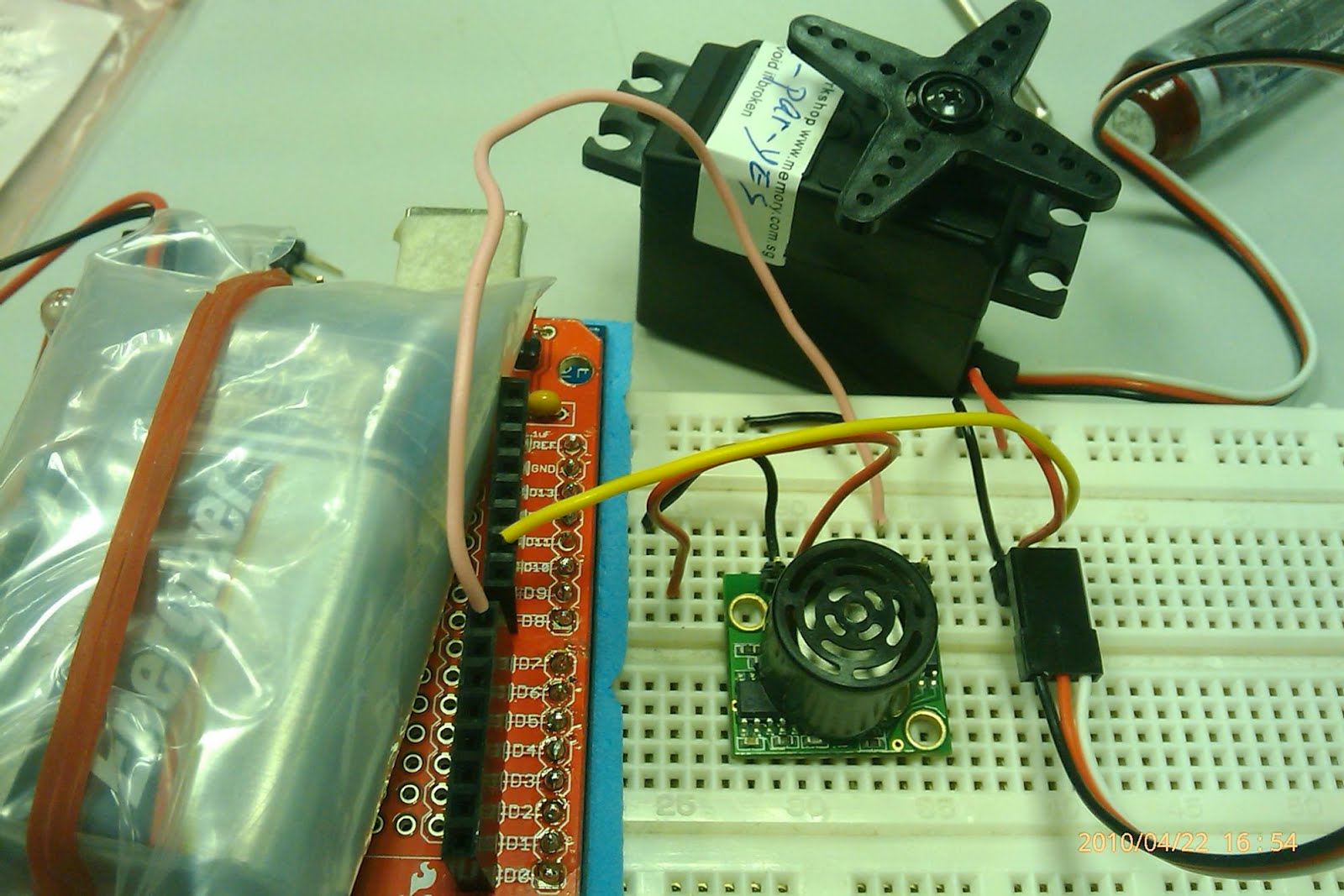
Connect MaxSonar pin 5v and Gnd to Arduino's 5V and gnd respectively. I am using Analog pin on max sonar, hence I connect it to A0 on arduino.
The ruler here is to help me to identify whether my readings are as accurate as possible. As I would put my hand across the sonar sensor at 15cm point and hopefully the readings will be 15cm too.
There are some sample code for sonar in arduino itself. I am using this from allen bruce. But he interface it to PING sonar instead.
The readings are plain crazy. 35x cm before I move my hand across the sensor. The analog pin is not accurate for short distance. But for longer distance where granularity in terms of 10s' of cm is still acceptable.
Next up, try with the PW pin. PW= pulse width. It is the Tc of the pulse generated by maxsonar that is measured. Wire to pin D8 instead of A0.
Same setup as previous. But the code have to change to reflect the method.
which cost USD$124 which is equivalent to SGD$162.44.
FYI, my wiimote cost me sgd$69 (left over from last year FYP project) and nunchuck sgd$25 (which I got from the shop at clementi city vibe where my student yenyu working part time).
Shall not elaborate about the wiimote and nunchuck...There are plenty of resources in the Internet.
I found out that the pin outs for the wii expansion port (WEP) from the Internet, thanks to the people that are willing to share the data! The drawing are for interfacing the IEEE1394 to the WEP.
Connect pin1 of WEP to Aref on arduino
pin2 of WEP to A5
pin5 to A4
pin6 to ground
I also found out that, it is not necessary to buy a nunchuck, cut out the connector part and used it with the wiimote. That, will render the nunchuck useless (to the Wii ofcourse, later you guys will find out more about my experiment with wiimote and why I have to use the nunchuck instead...........)
The replacement is a IEEE1394 male to male cable for sgd$7 from simlim square.
The pin out on the IEEE1394 and the WEP are carefully map out....
This is how it is going to look like, when they are connected...
Below are the code for sending and receiving data between arduino and pc. Similar code can be found at wiimeadows too! thanks to them for discovering the pattern of data send and receive out of the wiimote.
below are the ASCII art for the data flow of the devices that are hooked up together.
arduino ---wired--->wiimote--bluetooth-->PC
arduino <---wired---wiimote<--bluetooth--PC
Some way, some how, when I open my hyperterminal to observe the data output, I only receive my debug message which is "serial init finished". This means my serial connection of 119200 is setup correctly, but no generated data is observed. No subsequent data is collected both from the arduino through the wiimote to the pc (need to use 3rd party wiimote driver, such as wiimote library on the windows OS), nor the pc through the wiimote to arduino (through hyper terminal).
Used my multimeter to check the VCC and the gnd pin of IEEE1394 pin out, all seems to be correct. Just that no data is observed from the transferring between the devices.
Rewire the IEEE1394 again, with more meticulous effort put in... the result is still the same............................................
Fustrated, because if I can't get the accelerometer readings from the wiimote to arduino, my hypotheses of using it as my sensor would be false!!!!!!
I was contemplating to cut my nunchuck to retrieve the WEP PROPRIETARY connector..........because, I could still use the nunchuck on the wii (As if I got one, hahahah). If In the end, I decided to mutilate the nunchuck. Plug in the connector to the wiimote and the exposed end to the arduino.... No eureka moment.......... the data output is the same as the IEEE1394 cable........Very fustrated................................because of my hypotheses would failed..........................
But, which part went wrong?????? I am still finding the cause of it..........There are success stories on the Internet that used the similar setup.......
Before the last straw to be thrown, I tried to hooked up the nunchuck to the arduino instead.
with the code attached below
Atlas.... some readings from the accelerometer on the hyperterminal...data from the nunchuck.......
some years ago, i created a spinning LED display on my decommissioned hdd. I want to display message and time on the HDD while it spins. Basically I opened up the HDD, attached 7LEDs to it. Hook it up to a PIC16 which is the only MCU that is made available to me at that time. The result turns out to be very bulky, and I need to use a computer PSU (power supply unit) to on the HDD and a separate step down circuit for supply 5V to my pic16. During that time, I am still using a non-cam HP nor I have a camera and I do not document it down. BUT, the know how is already with me.
Ever since I got my hands on my arduino and my protoshield ready I have been toying with the idea of making 1 POV that is easy, less bulky and can fits in a palm in a snag. So that when I sing/dj in a concert, my fans would gyrate with their hands in the air and write a message for me with the POV (I hope is not asking me to stop singing!!). The EGO meter will shoot rocket high, so does my blood pressure. haha
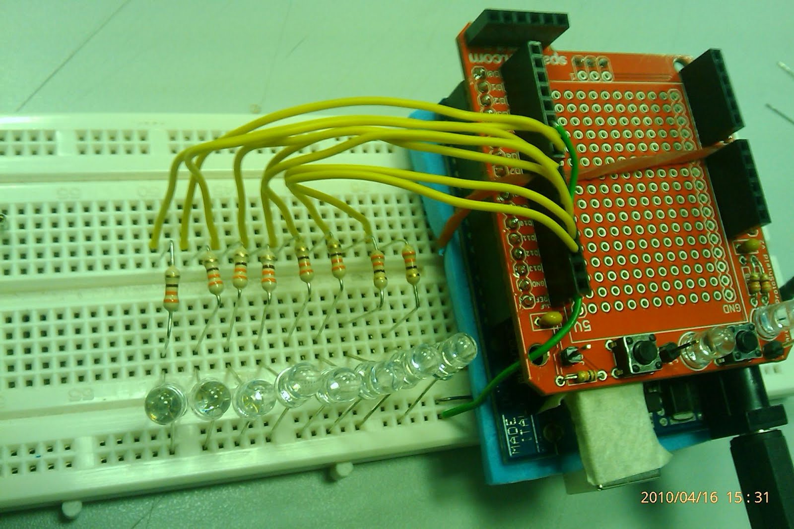
you would need 1x arduino+protoshield, 8x LEDs, 8x 330ohm resistor and code.
I am using the digital output of arduino, current limited by the resistor to the LEDs. This is how it will look like after hooking up all the components.
The Idea behind POV is to play a trick with the human eye. It is a known fact that human eye see things at a rate of 27Hz.
That is our eye's refresh rate. So anything that refreshes above that rate, the eye cannot notice the flicker.
Say I want to display the character "E" in a 8x8 matrix, the col is indicated with col1, 2 and so forth.
col1, 2,3,4,5,6,7,8
********
*
*
*****
*
*
*
********
I would light up the matrix column by column and each of the column is differ by 2.5ms (400Hz), this is only to light up 1 character.
If I want to light up a message say "EEE", I need to repeat it the process above for each of the character.
Straight away, I know that I need some form of loop control structure to display column by column, and character by character.
Furthermore, I too need a data structure to hold the message. The easiest way is to store the characters in a 2D array.
To make my life easier, I am using this website to help me generate the 2D array for the message to print.
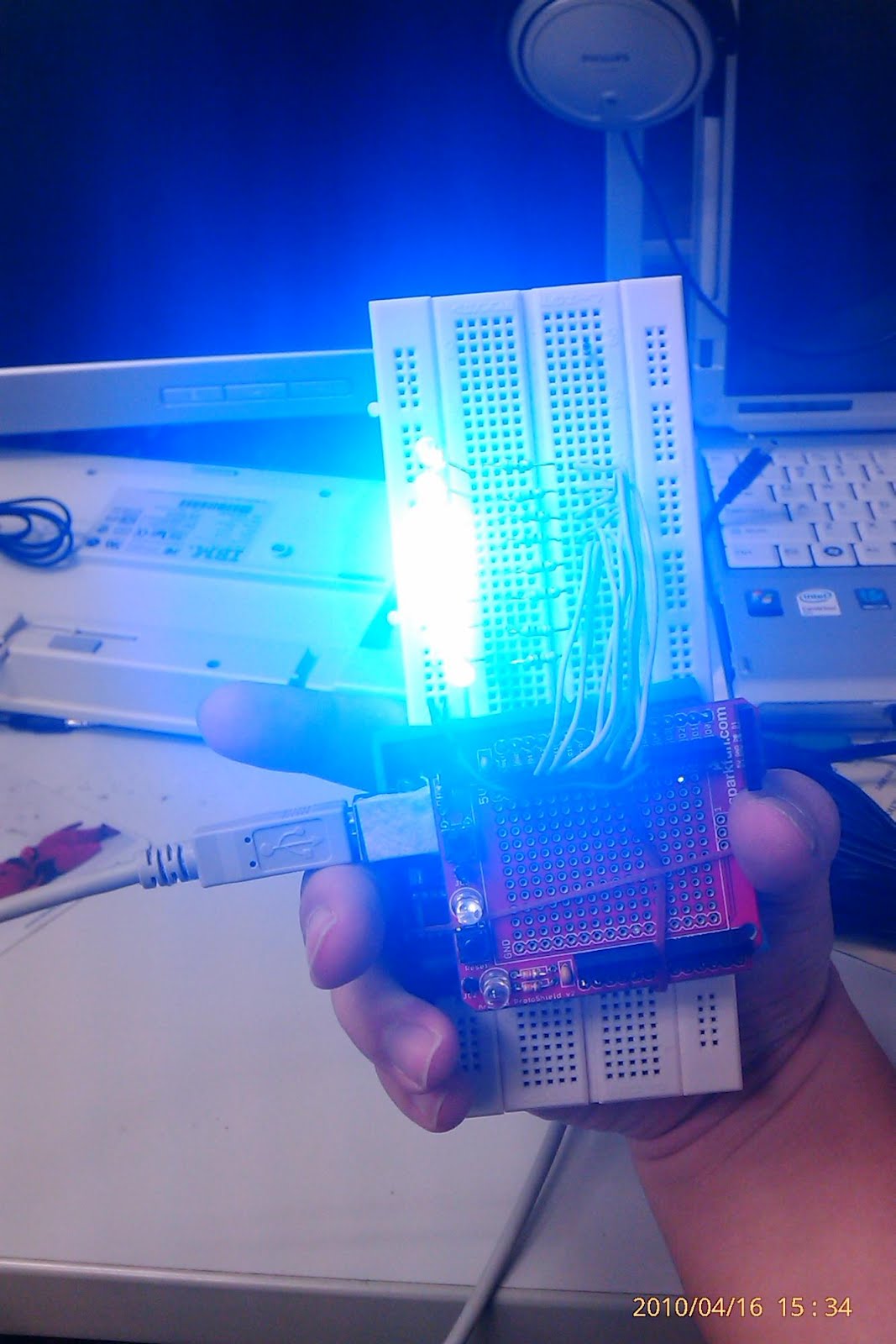
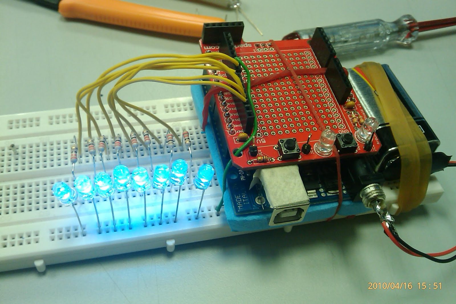
After finish programming, I need to test that all LEDs are working at the init of the code. It is cumbersome to swing the breadboard together with the USB cable. Hence I made a 9V battery connected for it.
Below is an example of POV.... note that I hold my camera upside down....
What message am I printing????
What can place you can think of to use with this "toy" ??
I was toying with the idea of buying an arduino http://www.arduino.cc/ for some time. It is one of the best open source MCU, complete with sample code and comes with 6 analog in and 6PWM (depends on the flavour). The best thing I liked about arduino is, it comes with many many "shield". Each shield serves a specific purpose, such as the motor shield, the ether shield etc. The shield package comes in a kit set. Hence, the low cost.
The price is not prohibitively expensive, but some how I spent my disposable income on my other research interest....Recently I got some cash to spare (not a windwall tho) and quickly approach my colleague Mike Ong to help me to contact his supplier get a set of protoshield and arduino. His supplier quoted me
Arduino Duemilanove = $52.80
Arduino ProtoShield V.4 Kit = $15.70
mini breadboard = out of stock
Good pricing! For $68.30, I can play it for a very long period of time.
So..... what is this protoshield alll about ?? Basically it is a mini development board for the arduino. Instead of using the big breadboard the store issued me and having many wires extending from the arduino to it. Sadly, the mini breadboard I wanted was out of stock....
The protoshield comes in a kit form. The PCB is of a very good quality, each description on the pin can be seen clearly.
Close up of the PCB
There is no instruction manual that comes together with the kit. Nevertheless, it is very straight forward to mount the components by reading the description on the PCB and do the soldering. The LEDs have their cathode filled off and it matches the pattern on the PCB.
Now, the soldering part. Secure the components with some sticky tape/masking tape or what ever tape that is convenient to you. Flip it over and let the soldering begin!
This how it looks like, arduino mounted with protoshield. Let alone the name sounds so coOOOooOOooOOoOL right!
I insulated the USB mini connector with some masking tape, because it is dangerously near to some of the points I soldered.
For the next 2 hours, I am playing with PoV (persistence of vision). Some of the staff, my project's boys and girls have seen it
I know I owe all of you the how-to. Writing a how-to actually takes more time then playing with it... *sigh*
I will try to write the how to for using the arduino IDE, that uses PROCESSING (another C-like programming language) and the how to of my PoV.
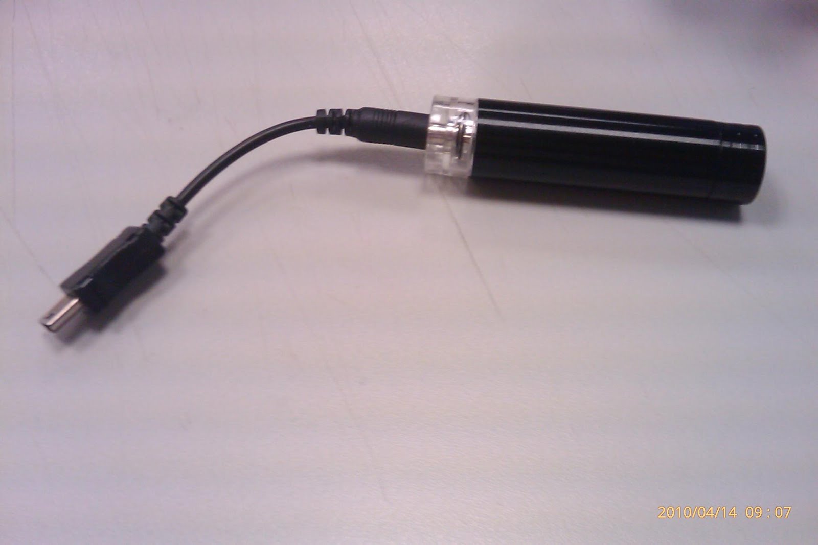
I received this toy as my christmas present (some present exchange game that too difficult for me to comprehend) last year. It is a handphone charger that is powered by a 1.5v AA battery. I tried it on my HTC magic... and it works. 1AA battery can charge about 5% on my phone.
I was tinkering with the idea of marrying the circuit in the AA battery charger with a kinetic to electric generator (aka the shaker) which works on the concept of rare earth magnet's magnetic flux is cut when it is moved in and out of a coil of enamel wires. http://en.wikipedia.org/wiki/Faraday's_law_of_induction.
The basic construction of the shaker is a rare earth magnet, sliding in and out of a magnetic tube that is coiled by some enameled wires.
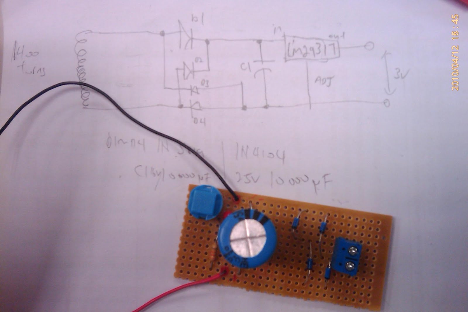
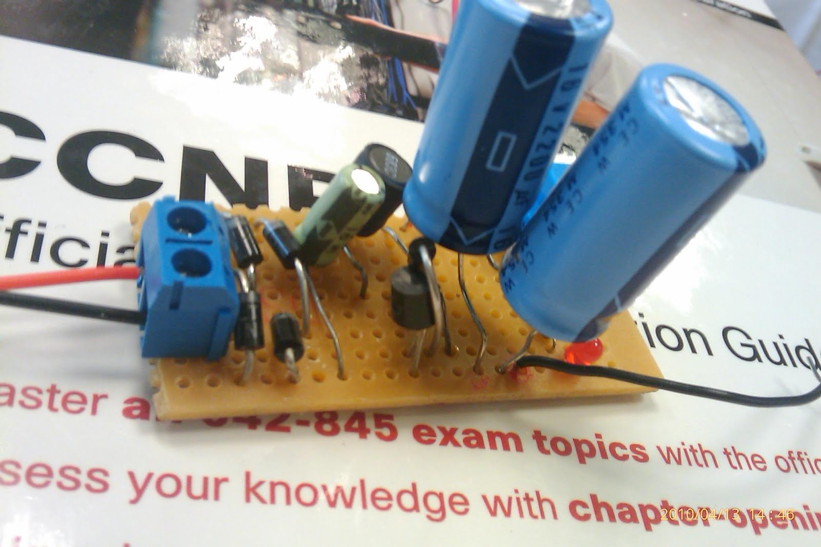
I also need a circuit that made up of 4 diodes (1N5819) and a capacitor (10000uF) to make the output into a constant DC. A voltage regulator LM29317 can be added too. Ai Ling the TSO is kind enough to provide me the components. thx!!. This circuit gave me about 3v across the load.
Since the AA charger only needs 1.5v, if I can supply constant 1.5v to the AA charger through my shaker, I would be able to charge my handphone for FREE!!! (assume cost of energy acquired from food is FREE)
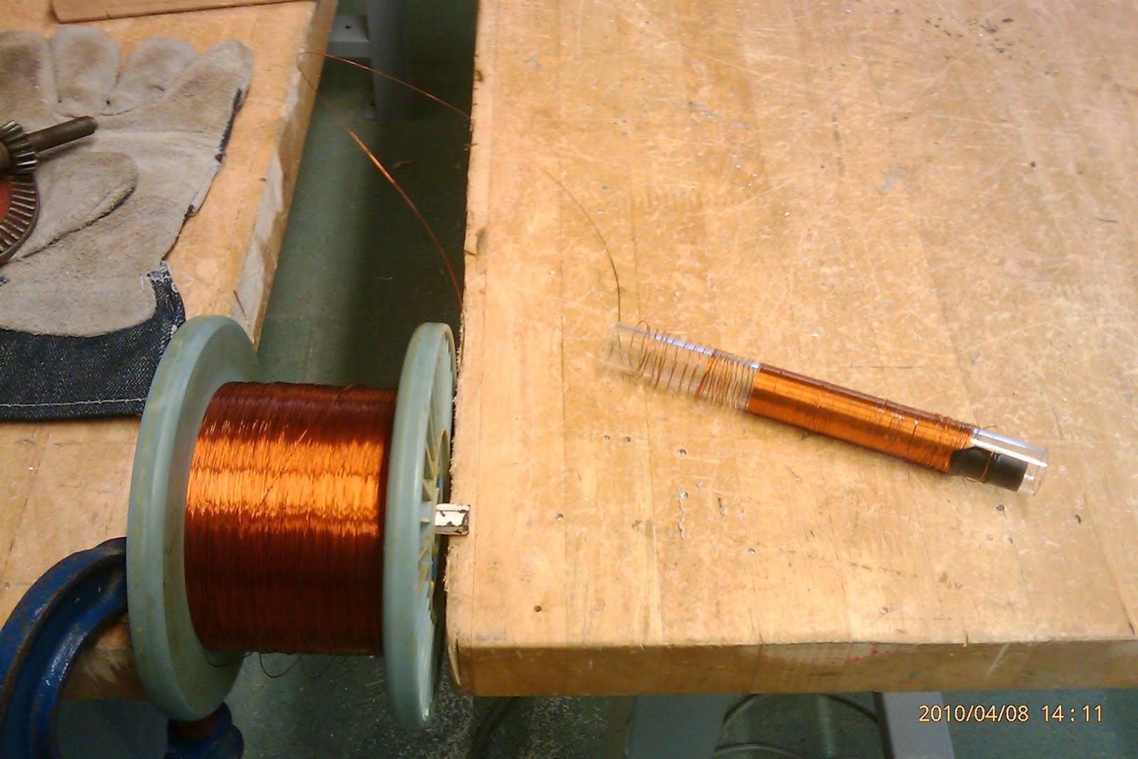
I got my rare earth magnet from a shop in sim lim tower basement 1 for $18. Use the remaining acrylic tube from my light saber project and now I need to coil 1400 revolutions of enameled wire on the acrylic tube. Ask around the lab TSOs for it and Hamzah show me some which is left over from a previous project. Now the challenging part is how am I going to coil 1400 times by hand!?
My first attempt trying to coil by hand... very tiring. Wanted to use a power drill, but none of the bits fit my acrylic tube......and I lost count after the 300th revolution.....
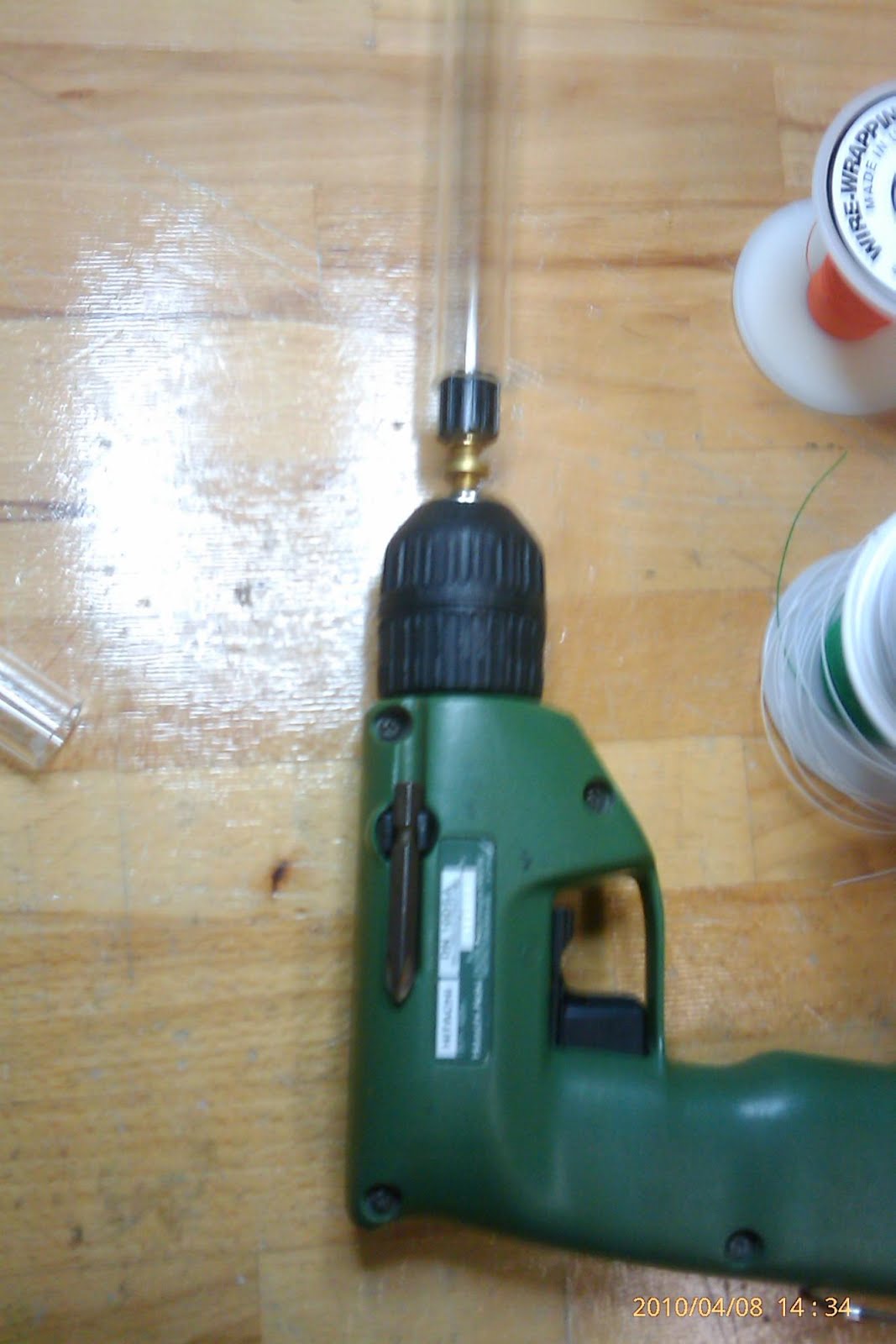
My 2nd attempt, with the power drill. The bit is a knob I salvaged from a variable resistor........
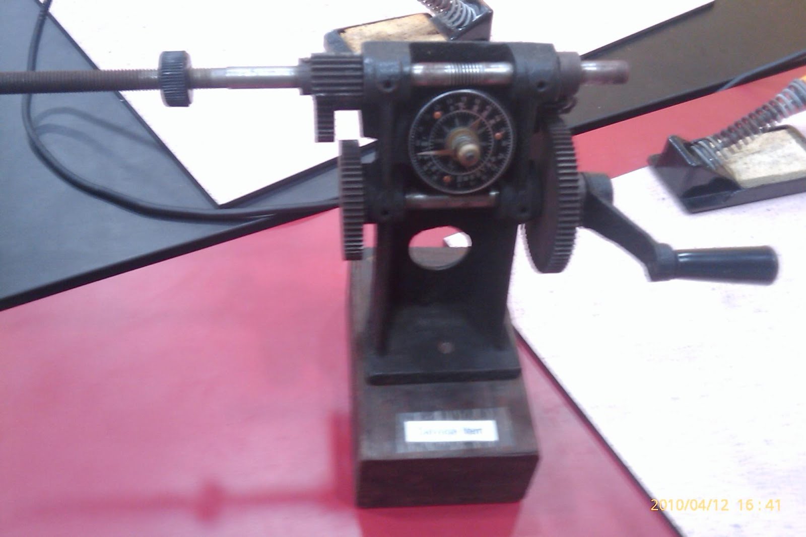
Apparently, there is this antique coiling device that is sitting somewhere in the cupboard at T12A406. I only discovered it after I have done coiling with the power drill....
I have varied the simple circuit of the above to provide better charge storing (2x capacitors) and capacitor to stabilize the input of the LDO .
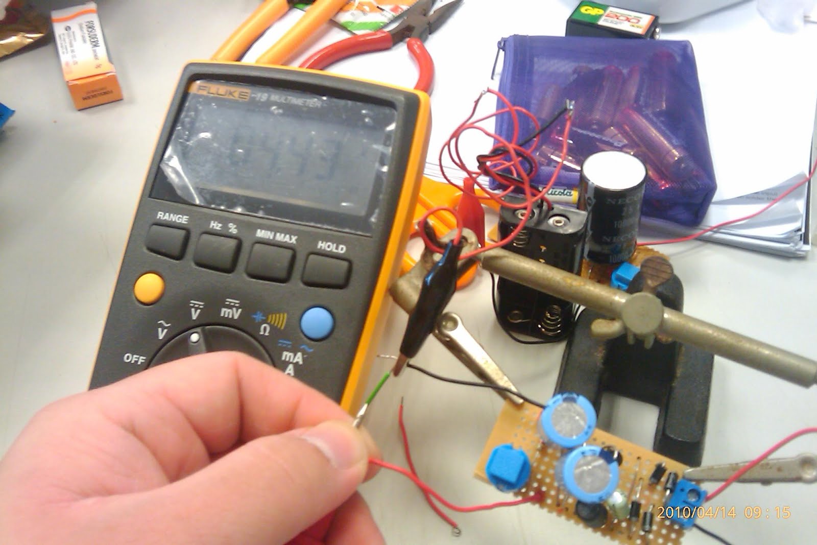
After couple of shakes............ not to bad, the voltage is 4.43v and current in the range of 0.9~1mA.
More then enough to power an LED, but how about charging my phone through USB????!!!
USB on my laptop provides 5v and 100mA per port to charge my phone. The current might be an issue here
After hooking up the output of this circuit to the input to the circuit of the AA battery charger then connect to my phone through the USB and after many many many many many many many many violent shakes, my phone is still not charging....
Voltage across the load is still 0v after many violent shakes. the capacitors are not building up charges as fast as the discharge....
My hypotheses might be WRONG!!!
with a sore arm, a dented ego and a finite FREE time to play with my hobby,
I brought it to BarCampSingapore5in SP, gave a flash talk on how to make it. the response was OK, there are some jedi out there in the crowd... One comment from the ground was.... where is the sound from the light saber. It suppose to have the VOOOOM sound every time the light saber is swing.
OK, Sim Lim Tower Here I come again!.........
there are 2 parts to solve this issue.
1. the mechanical motion detection switch
2. the voice/sound electronics.
item 1 was tricky to solve, because the COTS available is out of my reach. I tried to fabricate one with ball bearings and some metal plate, a close circuit will form when the metal ball bearing touch the metal plate. The outcome is not satisfying. I am using a roller switch instead.
item 2, i bought a "puma" voice digital kit for $8 at SLT, so that I can quickly hook it up to my light saber.
Sadly, on the first try, nothing worked!!!!
The troubleshooting begins~!~!
The transistor is configured as a BJT and act as an amplifier in the circuit, and the IC is the one that generates the sound. The kit's PCB (printed circuit board) and the IC chip does not contact properly, there is some miss alignment. Small issue I presume and I ignore it.
the voltage between base and emitter suppose to be 0.7v when it is in forward biasing, eg the transistor is working. But, i got a 0v reading on my multimeter. The best part, voltage between collector and emitter is 2.7v which is the voltage of my supply. it means that emitter and collector is shorted, e.g spoilt transistor.
All the other components tested fine, except for the chip alignment... small issue....I think....
Can't really sit down to trouble shoot, because in between office hours, I have to attend meeting and conference and the circuit is left at a corner paralyzed.......
When I got the time to fix it, Thinking that is the transistor fault, I swapped it with another spare I have. But I do not have the exact c9013 low power and have to used another NPN equivalent make the chip contact to the PCB closer with the use of the piece of paper as spacer. When I decide to cut the PCB to make sure the alignment is accurate and solder the chip's contact and the PCB contact
this is what i got... random noise.....
Is it the chip is spoilt, or the transistor i swapped is not working. The only good news, voltage between emitter and collector is not 2.7v and voltage between base and collector is 0.5v.
I deduce that, it should be the transistor, so I changed back to the default one and voila~!
I got my "PUMA" roar. but.......it doesn't sound like a puma, more like a creepy animal you watch on horror movie...
The whole idea of using a swappable chip is such that when i get my paws on the VOOOM sound chip, I can easily hook up to my circuit. Since now I solder down already to make the circuit more realiable, this is not any option. Nonetheless, I "wire wrap" it to my light saber.
this is my small button battery that gives 3v all together in the light saber. I did not share the 9v of the light saber coz i would need to use another voltage step down circuit (lazy lar duhz..... my excuse of not enough time..hahaha)