Friday, November 11, 2011

[arduino] RGB led, Introducing LOLSs

  Introducing LOLSs, an arduino shield made by my student lihsheng using uln2003a darlington.
LOLSs is an acronym, which stands for LED O' LihSheng shield. It uses 3PWM on arduino to control brightness of RGB LEDs. If we use digital output instead of PWM, we could only turn on and off the LED, which is ..... BORING. Supply is 12V, can support about 6RGB LEDS (that is 3x8 LEDs in total)
Behold...
 The component side of stripboard is soldered on the connecting copper side instead

Now about RGB LED, in each of them there are 3 LEDs in total which is Red Green and Blue. Red is 2.2v, Blue and Green is 3.5v. Hence we need to use resistors such as 150ohm and 80ohm respectively to limit the current. If not, the LEDs will be burnt. Here, I tested my RGB LED with 1.5v, hence the dim green colour.
 This is how the RGB led strip looks like. We would need a LED driver circuit to power up long stretch of them. LOLSs can drive up to 6RGB LEDs with 12v 800mAH NiCad battery.

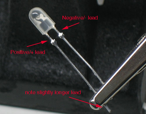
There are 4 "legs" from a normal LED, the longer leg is the anode which we connect the +ve side of VCC. The shorter legs are the cathode which we connect -ve or gnd.

Now, how can we wire the LEDs to the arduino?

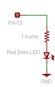
check out these diagrams by ADAFRUIT

Now, the fun part. Programming the RGB LED. We could do several of the below in code.
1. Light the colour one by one
2. Fade the brightness of the RGB LEDs with PWM. There is example code to fade 1 LED. It is available at Examples->Basics->Fade
3. Mix colour of the RGB LED. the value of RGB LED follow this format [255,255,255]. For each colour, 0 to turn off, 255 to turn on. Any values in between is to change the brightness. If all 3 led is 255, what is the resulting colour=? WHITE 
3. Make the colour change according to music
4.etc etc

Here is my rendition of RGB led with Arduino, based on the sample code given.


code here

Thursday, November 3, 2011

[game] Shogun2 Legandary difficulty playing for Tokugawa clan

I am playing Shogun2 since the last 2 months and you know what, medieval2 last me for a whole 3.1 years! I played all factions and difficulty level. lol


This campaign is VERY challenging. I got wipe out, annihilated, humiliated, sieged at 10:1 and more.
After a few tries for loosing at the 3-4th turn and the last 40game restarts I did not manage to clear the 30th turn mark.

Let me give some background information about shogun2 tokugawa clan at Legendary difficulty level.
I started off as vassal for Imagawa with 2000gold, 2 generals, 1unit of yari samurai, 2units each of yari ashigaru and ashigaru archers. I have a metsuke (secret police, good in maintaing order while taxing the population) too. Being a vassal means my overload gets 50% of my $$ and i can only wage a war which pisses off my boss. Politically, putting me at a very passive position. I will explain more later... less income means I can't afford big/elite armies. The whole objective of the game at the early stage is to shake off the vassal status by either Imagawa declare war on me, which hurts their daimyo reputation and diplomatic score or let other enemy rummage over Imagawa. Based on the art of war of sun-tzu, if I let my friend's enemy attack my "friend" and borders me too early, i am in big trouble. 唇亡齿寒


At the start of the game, Oda clan is my arch nemesis and they are marching on my land. Which means, my income from farm got affected, population unrest is higher=> bad and their army outmatch mine in terms of head count and eliteness!

After many many tries over the weekends playing the game, got wipe out then restarting game, experimenting with the opening strategy to outlast my overload. I think i got one of the effective "opening strategies".

At 1st turn. offer 20 turns or more of military access to neighbour such as saito and kiso for gold. the more the merrier. I got about 4000 gold for 20turns or 6000 gold for infinite turns. Offer to trade with both of the too, this will generate some income. While still a vassal, let other factions that border you pass your land for a fee. This will generate lots of income. Offer to marry Saito's ugly-greedy-evil-bitch daughter at 120gold (hey, i got 4000 from previous remember?). Straight away the relationship became "very friendly". By doing this , Saito will take Oda (hostile with each other) sooner and defuses the enemy marching on my land and later shadow me from the north against Hattori. With the newly acquired gold, i ordered my metsuke to bribe the oda clan's army that is on my land with 35% chance. A successful acquisition would cost me 3670 with 1unit of yari samurai and couple of the ashigaru units. Next, order my daimyo to attack the remaining Oda force to earn some bad-ass reputation (i always groom my generals to be the level of "intimidating", good for maintaining peace on newly acquired land.). Now the enemy retreated, I had a choice of pursuit Oda at Omi (very fertile land) or not. The fact is, with my current army I have a less than 50% chance of winning. Got to give it to Saito. Research on "chi arts", with the focus of getting my kishio ninja ASAP. These are the featured units for Tokugawa clan. Destroy the "rice exchange", so that the sake den could be build at the next turn. Build the farm land+1 upgrade to sustain the clan. Remaining amount of gold, recruit ashigaru archers but bear in mind the upkeep should not exit the next turn income. Hit next turn.

Turn 2-4. Build sake den. Train more arches. Research chi-arts to get my kishio ninja. Build trading port and start to send ships to explore for new commodities. Bear in mind, the army/navy maintain cannot be more than the next turn income.

Turn >4. Upgrade the sake den all the way till criminal syndicate. Behold, my Kishio Ninja. They are expensive tho. 884 for recruiting and 295 for upkeep. By now, Oda should be wipe out by Saito and Hatori is on the rise. Rule of thumb, try to save more gold for rainy days.

Turn 45. Hojo declare war on Imagawa, my overload. By now, i have some gold at about 2k, an army that could defend my castle and several ninja and metsuke. Here comes the intriguing part. I want to hold Izu the gold producing land held by Hojo and it's kinda far away. I want it so badly i would use my ninja to sabotage imagawa's marching army to delay it by 1 turn so that i could take Izu. But the bad thing is, Hattori would border/siege my castle to the west because Saito gave in to early. Eventually Takeda will then border Izu and overwhelm my castle with their elite calvary. Build a temple too, and the monks recruited could be use to cite unrests in rival land. The rebels will eventually overpower the owner and own the land and thus I would attack the rebels. Good way of taking their land without inciting war.

The AI in shogun2 is AWESOME, almost 50+ game restarts with different strategies i experienced different game play and still end up loosing at 70+ turn.

The only time i played until 100+ turn was I did not participate in the war against Hojo and my overload was killed, freeing me from my vassal status. With my monk+mesuke+ninja strategy i took many lands and maintained a chummy relationship with the owner which I took the land from. Awesome isn't it. Things went south when my favourite general Iyeyasu (historically, he created the tokugawa shogunate that runs for 265 years) and the next inline to be daimyo got sandwiched by Hatano, Asai and Kitabake while retreating to the nearest castle. Just a few more inches and he will be safe. Because playing at Legendary difficulty, i could not do a quick save nor a reload, I can't turn back time. Sounds like life huh?? After many set backs i resort to manually copy the save game file to create a "backup" which I found out later.


If you are interested to pick up from where I left with, here is the game saved at turn 45.
http://db.tt/5JD5ZfvS
paste it in the saves_game folder at C:\Users\"username"\AppData\Roaming\The Creative Assembly\Shogun2\save_games

share with me your strategies too~!
Tuesday, November 1, 2011

[Arduino] water sensor


I was tinkering with the idea of water sensing with arduino. The rain sensor / water sensing kit/ water detector/ is kind of hard to come by from the Internet stores. Courtesy of Mr.ChongSP, I get to sample his water detector PCB.
Thanks!
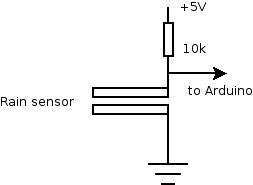
The concept of working is the gap between the PCB routes will close when there is a water droplet run across it. Water conducts electricity.  With the appropriate pull up resistor connected with the PCB kit as per the diagram below, we could get the components up within minutes.
Quickly I hook it up with my arduino and used the "button" sample code. i.e the switch button is now my water detector. If there is water, light up the LED, and if there is none off the led......


Now, here comes the interesting part.
1. instead of the usual project of "detect rain-retrieve-laundry" type of application, can we have something more interesting????? I have at least one in mind... hehe
2. is there a way i could do away with the PCB water detector, it looks kinda out of reach to me. Sure! how about using double row male PCB header?? hehe

Monday, October 10, 2011

[Arduino] Bi-Directional DC Motor Control With Arduino Only.

This is probably not the best way to get it done. Nonetheless, we could use Arduino Digital I/O pins configured for PWM to control a small little motor that is meant for solar use. The reason being, the current requirement for solar motors are much lower compared to tamiya motors etc etc at the toy scale.
The risk of frying the Arduino is much lower, but doesn't mean that it will not fry the arduino!

BEWARE of the risk involved as I am not responsible for your own doings.
Programming it is pretty straightforward but with a little twist on the understanding of PWM. Standard PWM outputs are used to the DC motor. If both PWM are arrive timely and "synchronized" i.e LHS is logic low and RHS logic high, the SMALL DC motor would see a complete circuit all the time. The small DC motor is tricked on seeing a +5v applied to RHS and gnd at LHS. To reverse the rotation from CCW to CW or vice-versa, just reverse the PWM outputs.

The goodness of having PWM output to the DC motor, the rotations could be control instead of just rotating at constant speed. Giving the users acceleration if needed instead of just velocity.

Now the mind boggling part. How to use the limited number of PWMs on arduino to control 2 small DC motors effectively ??  Try it but at your own risk!!

enjoy the 1 side motor


code here

[Arduino] Bi-Directional DC Motor Control

[Arduino] Bi-Directional DC Motor Control
As time to come, we need to control motor or maybe even motors using our arduino. The 40mA limitations on the arduino Digital I/O pins made the load for the projects somewhat limited to LEDs and small little motors meant for solar (mainly because these motors are low in current requirements). What if I want to control big motors and really BIG A$$ motors?

For tamiya motors (3~6v, <1A), I would recommend something such as the ArduMotor  shield available from sparkfun at the cost of USD$25.50 (retired from sales) or the MShield from adafruit at the cost of USD$19.50. I do have the luxury of using the earlier, add a heatsink with some thermal paste and run at 2A max per channel continuously before one of the wheel got stuck and fried one side of the shield. For really BIG A$$ motors at the range of 24V 10A, I used Sabertooth2x25 available from Dimension Engineering at the cost of USD124.99.

The issues with buying items from the Internet and to ship from US, the turn around time is toolong (or short at the expenses of the consumer), and vendors locally do not carry it in-stock. For simple motor driver circuits, it is just a L298 chip (or couple with L297 for stepper motor control) with the accompanying circuit. The real hassle is to wire it up on stripboard and solder it. Which deter many from getting it done.

I chance upon Mr.ChongSP’s D&I lab previously. Apart for the SSR kit, I also asked for the Bi-Directional DC motor control kit, which was meant for the PIC18 MCU sets. Thanks Mr.ChongSP!
pretty neat huh.

After soldering up the components, it is time to wire up the tamiya DC motors to the motor controller to the arduino. Making the ribbon cable connector break out cable is such a chore and demanding on the eyesight. Luckily I got student junhan to help me on it.
Attach the power source. +5v to the motor control (VSS) and >5v for the motors (VS).

Upload the code to Arduino and waiting for the magical moment...... after 2mins... still no sound, no noise and the motor control L298 is totally cool to touch. Something is very wrong here. Check connection, check code, check corresponding pin on motor control board to arduino and to code , just in case there is a mix up. No fault found. A quick check using the Digital Multimeter, only 0.2V measured across the DC motors. Seems to be dry cells I am using the current is not enough to drive the tamiya dc motors. Thus I swap to a 8.4v 200mAh GP rechargeable, only 1 side of the motor is driving. LOLx

A quick swap to conventional DC motors
Pheww... it worked


Time to source for some LiPO cells to play with my tamiya motors setup with the Bi-Dir Motor control board!

source code with comments here

Friday, October 7, 2011

[Arduino] Solid State Relay ( SSR )

[Arduino] Solid State Relay ( SSR )

Currently the DIY PRT prototype uses a HUMANGOUS 24V 10A mechanical relay + transistor circuit to switch between the 5V MCU digital pin and the 24V 10A DC supply to the motors.

In the next step of modularizing the building blocks of the DIY PRT into an Arduino Shield, that AWESOME relay could not fit into the shield. Worst part of it, the EM generated by the motors traversed the wirings and this affect the reading of the sensors. Previously, sparks was observed in the mechanical relay when the circuit turned on while the wheels were locked accidentally. If working in enclosed environment with dangerous gases (not fart pls), the spark might cause an explosion...Worst of it, there is no isolation of high current high voltage circuitry from the low voltage low current MCU. The circuit run a risk of frying the components at the low voltage low current side. Well, unless the opto-isolation circuit (opto-coupler) is included. The circuit get more and more complicated with each additional feature added!

The challenge here is to reduce the size of the relay, have opto-isolation and also simplify the circuit. SSR is here to the rescue~~~ http://en.wikipedia.org/wiki/Solid_state_relay
_________________________________________________________________________
One day while running some errands outside the office, I chance upon a SSR circuit from Mr.ChongSP’s D&I lab. It was displayed outside the lab.

Using my thick-skin-jutsu i approached the lab TSO and executed my BBS move on her. Mr.ChongSP and TSO Ms.Jana were more than happy to supply me a set of the SSR kit. thx! Look at the timestamp of the pictures, It took me more than a month to acquire, experiment and write down the experiment. Time is a rare commodity (exam, marking, checking, tallying, data entry, checking again)….If you have some spare CPU cycles, consider to supply me some.
The TSO reminded me that this PCB connection is meant for DC-DC switching from low voltage to not so high voltage.  But according to the specsheet of the omron SSR (I love omron relays!) http://www.omron.com/ecb/products/pdf/G3VM_351BE.pdf
This babe is capable of switching to 280V 100mA !!! Just to be safe, I only try to turn on a LED. lol. A quick peek at the specsheet, this babe is capable of switching DC-DC and also DC-AC depending on the configuration.
Soldering the PCB is pretty straight forward with the detail explanation on the silk screen. A point to note, when soldering ICs’ , never mount the IC to the IC holder while soldering the IC holder to the PCB. The heat form the solder might damaged the IC. An advise from my lab TSO many many years back when I was a student here. IMMA such a good student @@”
Only plug in the SSR when all the soldering is done.

Pretty neat huh...


Now, connect the GND pin from the PCB to GND pin on Arduino (I found some students make this mistake when wiring up stuffs... The consequences may range from very small such as circuit not working to very serious such as sparks and fried MCU), VCC pin to 5V on Arduino and lastly signal pin to any one of the digital output pins on the arduino.

As for the code, I use the example code found at File->Example->Digital->Blink.
The SSR will be triggered at specific interval, turning on the LED. Phew.... everything work at 1st try. Now, time to wire this SSR to more interesting hardware (<10 V load plssss). Interested to play with it ????? dXD

Tuesday, August 16, 2011

[Java] Credit Card validity checker using Luhn and known MII

I received an email from Mr.Chua yesterday seeking help on behalf of "dignitykitchen" to address the matter on
1. whether there is a way to differentiate the various credit/debit cards eg. AMEX, VISA, DINNERS etc?
2. Is it possible to read the card to get the card number and tell the type of card?

Suddenly the thought of using this as a case study for Java programming I assignment crossed my mind. 

Nonetheless, I could not wait till next semester to start to code and quickly hack up a POC using Java for Mr.Chua. Usually, I code in C++ or python, since we are going to learn Java Programming I soon therefore I shall code more often in Java. The implementation can be ported on C, C++, Java, python, android, arduino (to hook up with a magnetic card reader, more later) etc. As long as the programming "logic" is sound, it can be demonstrated using different language. It is analogous to saying "I love you" in different language..... You get the idea.

The code uses luhn algorithm to check the validity of the credit card number, through a series of steps on choosing alternate number starting from the LSB, perform calculation and finally a MOD10 . The code does NOT check the validity of the card with the credit provider. Features such as manual input, identifying credit card provider were added. The code base can be expanded to recognize more info from the number itself. 

Apparently I misinterpreted the word "read" from the email received, after realizing it from another colleague's suggestion on using magnetic card reader with an MCU to "read" in the data from the card and do the validation checks on the MCU iteself. Anyway, the validation code can be ported to the said MCU... e.g Arduino with a magnetic card reader.

NOTE: Source code is for academic use only.
1. place Main.Java and LuhnCheck.java in the same folder. Compile (I did it using javac) and run.

Main.java

Luhn.java

there goes my lunch time...... duhz.....

Sunday, July 24, 2011

loading external *.JS as per XSS

test external *.js, for the different flavours of XSS

">

Friday, July 8, 2011

[DIY] Arduino VU Spectrum Analyzer

While searching on the Internet on interesting way of approaching the purpose of doing Fourier transform and why we need FT for my teaching.

I came across a fellow arduino user (http://andydoro.com/vulol/) that posted his toy project on using Fast Fourier Transform (FFT) to make a VU meter. Couple of years back, I did played with my home made wireless VU using electronic components that is available from the store. I am quite surprised that  an 8bit Arduino is capable of doing FFT, never did I thought of using it because usually I am using a PIC32dsp for transforming from time domain to frequency domain for signal manipulation purposes. Arduino did gave me the WOW moment for a while.

From the detailed explanations on his website , i downloaded his code and hook up my LOLshield on my laptop playing some song to enjoy the geekness of arduino LOL shield VU meter.... To my dismay, it doesn't work "out of the box". It just display a 1 liner.... both plug in to my laptop and plug out from my laptop. Seems that the VU only picking up white noise from the ambiance. The connections are correct, pin A5 for +ve signal from the left channel and ground to common ground of the mini stereo jack. 


To further complicate the issues, I tried on a variety of input of devices ranging from my android phone, my speakers with a BIG ASS amp etc. Suddenly IT hit me, probably the analog signal read in at pin A5 is too low to be detected as a usable base band signal where the FFT would chop up the signal in time domain to be put into frequency domain and the harmonics combined as 14 outputs (LOL shield only have 14 columns of LED).

There are 2 ways to put the analog in on steroids. The hardware method, I would use a TIP31C or TIP41C audio amplifying circuit OR the software method by scaling up the data read in on A5. I choose the software method, it requires little time to prove my hypotheses compared to the hardware method.....

It is kind of worrying.... the VU is more sensitive now ,picking up ambiance noise which is reflected in the below picture. The LEDs are lighting up ....More work needed to change part of the code to filter AWGN....

But once I plug the mini stereo jack to a Y connector with the headphone stereo jack into my laptop, the noise signal disappear.
Played one of my favorite songs with rich sound texture... Sorry for poor sound quality... I am playing it through my headphone.... still office hour and I can't turn on the LOUD music...


enjoy the code. you would need to place the FFT and charlieplexing libraries in your arduino\lib\ folder to compile successfully.

Saturday, June 18, 2011

BGP awesomeness with Packet Tracer 5.3.2

With Packet Tracer 5.3.2 you can experiment with BGP (eBGP)

It serves as a good tool for a refresher, especially for poor chap like without exclusive access to the cisco racks....


Here I demo Cross AS BGP. Not all the BGP peers have a direct peering. I use the "network" command to do the routing.

Common mistakes that might occur
1. Peering with BGP peer on the wrong AS
2. Peering with BGP peer on the wrong IP subnet
3. Configure wrong AS for BGP on the victim router
4. and the list go on....

to verify your settings...
sh ip bgp

sh ip bgp neigh

come code for your reference.....

Wednesday, June 15, 2011

my first attempt: solar cooker

Get a BIG cardboard, some aluminium foil and adhesive.
1 black or dark colored cooking vessel.
1 small piece of wood as insulator.
1 clear plastic bag. I got mine from the fresh fruits section at NTUC... but realise it was a lil too small to fit the flower pot I am going to use.


We are going to form a cone shape with the cardboard, hence make a cut with a diameter of 25cm or more to accommodate it. Paste the foil on the cardboard, shinny side up. I made a mistake of inverting it....oh well...

I was hunting for a pot like apparatus to secure my new toy... Went hunting around and discover some flower pots......


weather check.... it was cloudy.... not a good day for solar cooking....

I am experimenting whether solar cooking rice or sweet potato will be edible? Typical Asian staple.

arrange in this order and secure with cable tie.

/\
/ \
/ \_______
| air |
| |
|cooking ware|
| insulator |
|plastic bag|
-------------


Just in case you guys wondered where did the flower pot went to ...

Cooking time -> 1245 - 430pm...
the plastic bag burst....

Conclusion.....
The rice is not cooked..... but the rice water is warmer then room temperature.
The sweet potato is not cooked thoroughly. Never buy $1 sweet potato from NTUC... rotten ...

next up.... improvised on
a. neater foil reflector will lesser creases when pasting it to cardbord.
1. weather check appratus..
2. temperature check apparatus....
3. quantify the heat generated from this solar cooker.. (a lil far fetched)

Thursday, May 19, 2011

kit set amp for old Sony speakers

So there were 2 VERY OLD, DUSTY (at least 1" thick beneath the cover!!) and UNAPPRECIATED Sony speakers that one day magically appeared in our T902 club hauZ. Seems that somebody conveniently let this GOOD SPEAKERS rot in an isolated corner, get kick around and UNLOVED.


Upon close inspection, the speakers are still usable. Well, at least the leads to the + and - terminal are still intact and no sign of corrosion from the moisture yet. To make these bad boys start to sing angelic tunes AGAIN, I need something to amplify the audio signal from iPod, laptop, android phones etc (not necessary be mine laaaaa). By plainly hooking the other exposed end of the mini stereo jack to the speaker’s 2 terminal won’t yield any sound. Better luck if the speakers are hooked up to a 2kHz function generator.


I need an AMP as cheap as possible. There is no luck finding the original Sony ones. Obviously, it was dumped because of the spoilt amp and hifi system. Try making one amplifying circuit from components from the lab, e.g some TIP31C, R&C ? Too time consuming and the amplified signal produced may only yield <1W from these big ASS speakers. We need something that can yield 8W from the circuit. A quick look at the store, no such IC’s readily available..... Some shopping is seriously needed at your friendly Sim Lim Tower......... After some browsing at the kit set’s section, I came across a 8W amplifying circuit kit set complete with good quality PCB with routes thick enough to pass high current, BIG heat sink and the best part, it is only s$17.50. After laying my paws on it, I hurried back to office can’t wait to start work on it.


The I/O parts are not supplied in the package, just few pieces of measly bare copper connector. I modified the inputs to a 3.5mm Stereo jack for the convenience's sake of plug to a laptop/android/iPod etc. As if it is going to be the headphone, albeit a BIG one. As for the power jack, it is done using a DC power jack with the +ve leads in the inner ring. DO NOT SOLDER or CONNECT inversely ! Outputs, I used some screw down terminal blocks meant for PCB. Too bad the PCB is designed for the above mentioned copper. I got to cut the terminal blocks to half to use it. Make sure to stick some tape on the components side, this is to prevent the components from falling out of place when soldering.

Fire up the soldering gun and start soldering......


Next up, I need a power supply that can supply 12V DC for 1A. My unloved HP charger can only go up to 6v and 200mA. I quick dive into my pile of junk and tadahhhhh... I found a dc wall adapter that satisfy the requirement. Lesson learnt, do not discard the old parts. It may come handy some day. I also added my VU meter which i made many years for practising my soldering skill. Now we got LED light indicators on the sound

Hook up the dc adapter, stereo jack to laptop and speakers to the amp circuit. Enjoy!
On a side note, the boys hook up this set to their home made projector and now we got a poor man’s cinema complete with “dolby digital surround” (speakers on the floor facing wall and reflectors to create the effects)!

What's neXt? Tube Amplifiers ???? teeeheeeheeeee


Tuesday, February 8, 2011

exercise code

refer to your year1 structure programming book

1. pg 121 . create a new function that calculates the difference of 2 numbers

2a. pg 146. modify the code to use a vector instead of an array.
2.b. pass by reference the vector to a new function to add 5 into each elements of the vector. Cout the vector in the main() to verify the value.

Tuesday, January 25, 2011

[DSA] binary tree

terminology
the root: the beginning of a tree.

every node is possibly the root node for the nodes below it. eg. the parent node.

parent node, the n-1 lvl of the n's lvl node.
child node, the n+1 lvl of the n's lvl node.

(n-1)
|
___n____
| |
(n+1) (n+1)

edge, the path for traversal to happend.
leaves, the lowest lvl in the tree.

a binary tree, a tree where each parent node only have 2 children.

binary search tree (BST)

a binary tree, where the root node is always the middle value of the list of values.

remember binary search from previous week?
what are the 2 possible condition to be satisfied before one can qualify for binary search?

BST it self is not efficient. there is a possibility that the insertion of the node will cause it to behave like a worst case binary tree.

we need a sorted BST, where each time a node is inserted the tree is "sorted" to find out which is the new node. What are the implications if the tree are always sorted when insertion or deletion is done??? Is there any other possible way to enhance it?

3 ways for tree traversal
-Inorder
Traverse the left subtree
Visit the current parent
Traverse the right subtree

-Preorder
Visit the current parent
Traverse the left subtree
Traverse the right subtree

-Postorder
Traverse the left subtree
Traverse the right subtree
Visit the current parent


uses of binary tree data structure
- compression
- encoding
- conversion of mathematical formula to prefix or post fix form
- data structure of choice for "fast" retrieval of search items

there are many other type of binary tree
full binary tree
perfect binary tree
balanced binary tree
self balancing binary tree

Monday, January 24, 2011

[DSA] map and set container


map<string,int> mapp;
map<string,int>::iterator mit;
string name_search;

    mapp.insert(map<string,int>::value_type("Amy",81377442));
    mapp.insert(map<string,int>::value_type("Bob",32731631));
    mapp.insert(map<string,int>::value_type("Catherine",32387163));
    mapp.insert(map<string,int>::value_type("Danny",21321312));
    mapp.insert(map<string,int>::value_type("Ecuador",54543947));
    mapp.insert(map<string,int>::value_type("Felicia",32535612));
    mapp.insert(map<string,int>::value_type("Genie",24172312));


refer to above on how the map data structure is used.


use the map data structure to satisfy the following requirements.
1. create a phone book application that can store name and phone number.
1a. perform a display all entry in the phone book.
2. phone number need to that ensure it is 8 numerical digits only.
3. initialize the phone book application with some data.
4. perform a lookup for a random entry in the phone book and display it.

challenge
5. Suggest a method to store address, email and msn address to the phone book that you have already created.
6. what are the advantages and disadvantages of your method??? explain why you choose the design.

Tuesday, January 18, 2011

[DSA] searching


Have you ever tried to find something in your house/room. Yet can't seems to ever find it. Now, lets not talk about misplacing items out of carelessness. Let's discuss how to "find" items in your wardrobe.

Assume you have your apparels hanging in the wardrobe, how would you "find" your favorite shirt/dress? would you start looking from the left hand side? the right hand side or simply in the middle???

If you find 1 apparel at a time from either direction, that is linear search. The worst case scenario is, you would traverse all your apparels before finding your favourite.

If you have sorted your apparels according to a certain sequence, eg, warm colours to the right and cold colours to the left, you can simply start finding from the middle, then to the left if your favourite falls in the cold colour. This is binary search. searching time can be reduced significantly.

Again, if you do like what i did, simply pile up all my apparels in the wardrobe without sorting/folding/ironing it. "Finding" for a particular item in the wardrobe can be disastrous.


Linear Search => O(N)
Go through the entire array of items to lookup on the searched key. The sequence of items are not sorted.
Best case , the 1st item in the array.
Worst case, the last item in the array.
Average case, traverse for half of the array

Binary Search => O(logN)
Uses a divide and conquer method.
array of items must be sorted first, involves a cost.
L <> root
|---|---|
L---M---R


For any array of 1000000 items, Linear search need 500000 comparison (assume an average case), Binary Search 20 comparison.

Pop Quiz
1. Create a generic code of linear search to take in different data type.
2. Create a Binary Search tht uses recursive method.
3. Use find() or search() from the STL to do a lookup of a string, among many strings stored in the memory

Monday, January 17, 2011

[DSA] Sorting


Here comes the interesting part in algorithms.
Sorting and searching are the crowns in the algorithm topic. So to speak, these are hottt topics for research in computer science world.

Efficiency, cost. Remember???

We will be examining bubble sort, insertion sort, selection sort and merge sort in details. Studying the complexity of the above algorithms, and not forgetting the implementation of the algorithm. Both DIY code and STL.

But Why Bother to Sort?


Here comes the question>>>>>>>>>

1. Implement sort descending for Bubble Sort, Selection Sort, Insertion Sort, STL sort. Use int arrays or vectors to try it out.

2. In our session, we use integer to demonstrate sorting. Is it possible to sort characters, strings, double, objects etc? Use vector or arrays to try it out.

3. Use the sorting algorithm of your choice, sort 10 tropical fruits of your choice.

4. On top of the previous implementation, create a class for fruits with 2 parameter namely int price and string fruitName. Sort the 10 tropical fruits according to fruit name or price. Your implementation should be able to sort both price and fruitName ASC or DESC. A menu might help in here.

5. Lastly, what considerations when we need to ponder when comparing 2 arbitrary Sort Algo A and Sort Algo B. How would we really know that A is better then B ?

There might be more then one implementation of the above sorting algorithm. Below are my flavor for the 3 algorithm. Codes are commented for easy following.
//bubble sort

//insertion sort

//selection sort

//merge sort