[Arduino] Bi-Directional DC Motor Control
As time to come, we need to control motor or maybe even motors using our arduino. The 40mA limitations on the arduino Digital I/O pins made the load for the projects somewhat limited to LEDs and small little motors meant for solar (mainly because these motors are low in current requirements). What if I want to control big motors and really BIG A$$ motors?
For tamiya motors (3~6v, <1A), I would recommend something such as the ArduMotor shield available from sparkfun at the cost of USD$25.50 (retired from sales) or the MShield from adafruit at the cost of USD$19.50. I do have the luxury of using the earlier, add a heatsink with some thermal paste and run at 2A max per channel continuously before one of the wheel got stuck and fried one side of the shield. For really BIG A$$ motors at the range of 24V 10A, I used Sabertooth2x25 available from Dimension Engineering at the cost of USD124.99.
The issues with buying items from the Internet and to ship from US, the turn around time is toolong (or short at the expenses of the consumer), and vendors locally do not carry it in-stock. For simple motor driver circuits, it is just a L298 chip (or couple with L297 for stepper motor control) with the accompanying circuit. The real hassle is to wire it up on stripboard and solder it. Which deter many from getting it done.
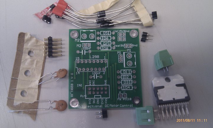
I chance upon Mr.ChongSP’s D&I lab previously. Apart for the SSR kit, I also asked for the Bi-Directional DC motor control kit, which was meant for the PIC18 MCU sets. Thanks Mr.ChongSP!

pretty neat huh.
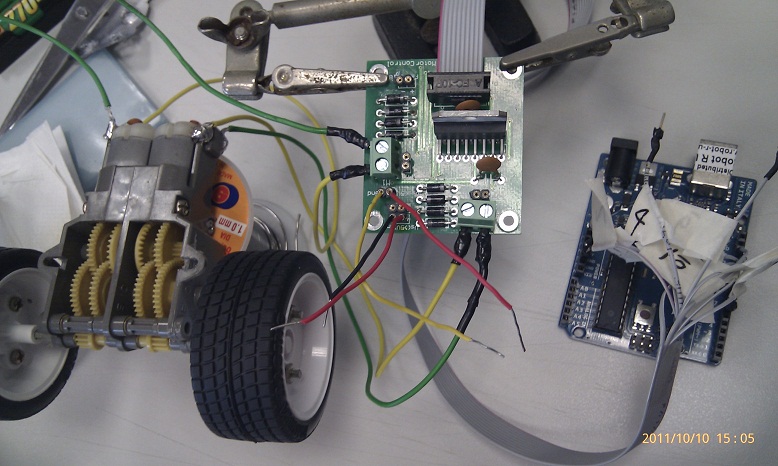
After soldering up the components, it is time to wire up the tamiya DC motors to the motor controller to the arduino. Making the ribbon cable connector break out cable is such a chore and demanding on the eyesight. Luckily I got student junhan to help me on it.
Attach the power source. +5v to the motor control (VSS) and >5v for the motors (VS).
Upload the code to Arduino and waiting for the magical moment...... after 2mins... still no sound, no noise and the motor control L298 is totally cool to touch. Something is very wrong here. Check connection, check code, check corresponding pin on motor control board to arduino and to code , just in case there is a mix up. No fault found. A quick check using the Digital Multimeter, only 0.2V measured across the DC motors. Seems to be dry cells I am using the current is not enough to drive the tamiya dc motors. Thus I swap to a 8.4v 200mAh GP rechargeable, only 1 side of the motor is driving. LOLx
A quick swap to conventional DC motors
Pheww... it worked
As time to come, we need to control motor or maybe even motors using our arduino. The 40mA limitations on the arduino Digital I/O pins made the load for the projects somewhat limited to LEDs and small little motors meant for solar (mainly because these motors are low in current requirements). What if I want to control big motors and really BIG A$$ motors?
For tamiya motors (3~6v, <1A), I would recommend something such as the ArduMotor shield available from sparkfun at the cost of USD$25.50 (retired from sales) or the MShield from adafruit at the cost of USD$19.50. I do have the luxury of using the earlier, add a heatsink with some thermal paste and run at 2A max per channel continuously before one of the wheel got stuck and fried one side of the shield. For really BIG A$$ motors at the range of 24V 10A, I used Sabertooth2x25 available from Dimension Engineering at the cost of USD124.99.
The issues with buying items from the Internet and to ship from US, the turn around time is toolong (or short at the expenses of the consumer), and vendors locally do not carry it in-stock. For simple motor driver circuits, it is just a L298 chip (or couple with L297 for stepper motor control) with the accompanying circuit. The real hassle is to wire it up on stripboard and solder it. Which deter many from getting it done.
I chance upon Mr.ChongSP’s D&I lab previously. Apart for the SSR kit, I also asked for the Bi-Directional DC motor control kit, which was meant for the PIC18 MCU sets. Thanks Mr.ChongSP!
pretty neat huh.
After soldering up the components, it is time to wire up the tamiya DC motors to the motor controller to the arduino. Making the ribbon cable connector break out cable is such a chore and demanding on the eyesight. Luckily I got student junhan to help me on it.
Attach the power source. +5v to the motor control (VSS) and >5v for the motors (VS).
Upload the code to Arduino and waiting for the magical moment...... after 2mins... still no sound, no noise and the motor control L298 is totally cool to touch. Something is very wrong here. Check connection, check code, check corresponding pin on motor control board to arduino and to code , just in case there is a mix up. No fault found. A quick check using the Digital Multimeter, only 0.2V measured across the DC motors. Seems to be dry cells I am using the current is not enough to drive the tamiya dc motors. Thus I swap to a 8.4v 200mAh GP rechargeable, only 1 side of the motor is driving. LOLx
A quick swap to conventional DC motors
Pheww... it worked
Time to source for some LiPO cells to play with my tamiya motors setup with the Bi-Dir Motor control board!
source code with comments here

1 comment:
I like it. Just got the shield for arduino, but need to make my own.
Post a Comment