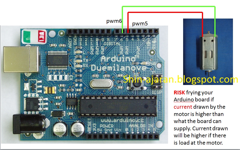
This is probably not the best way to get it done. Nonetheless, we could use Arduino Digital I/O pins configured for PWM to control a small little motor that is meant for solar use. The reason being, the current requirement for solar motors are much lower compared to tamiya motors etc etc at the toy scale.
The risk of frying the Arduino is much lower, but doesn't mean that it will not fry the arduino!
BEWARE of the risk involved as I am not responsible for your own doings.
Programming it is pretty straightforward but with a little twist on the understanding of PWM. Standard PWM outputs are used to the DC motor. If both PWM are arrive timely and "synchronized" i.e LHS is logic low and RHS logic high, the SMALL DC motor would see a complete circuit all the time. The small DC motor is tricked on seeing a +5v applied to RHS and gnd at LHS. To reverse the rotation from CCW to CW or vice-versa, just reverse the PWM outputs.
The goodness of having PWM output to the DC motor, the rotations could be control instead of just rotating at constant speed. Giving the users acceleration if needed instead of just velocity.
Now the mind boggling part. How to use the limited number of PWMs on arduino to control 2 small DC motors effectively ?? Try it but at your own risk!!
[Arduino] Bi-Directional DC Motor Control As time to come, we need to control motor or maybe even motors using our arduino. The 40mA limitations on the arduino Digital I/O pins made the load for the projects somewhat limited to LEDs and small little motors meant for solar (mainly because these motors are low in current requirements). What if I want to control big motors and really BIG A$$ motors?
For tamiya motors (3~6v, <1A), I would recommend something such as the ArduMotor shield available from sparkfun at the cost of USD$25.50 (retired from sales) or the MShield from adafruit at the cost of USD$19.50. I do have the luxury of using the earlier, add a heatsink with some thermal paste and run at 2A max per channel continuously before one of the wheel got stuck and fried one side of the shield. For really BIG A$$ motors at the range of 24V 10A, I used Sabertooth2x25 available from Dimension Engineering at the cost of USD124.99.
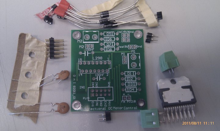
The issues with buying items from the Internet and to ship from US, the turn around time is toolong (or short at the expenses of the consumer), and vendors locally do not carry it in-stock. For simple motor driver circuits, it is just a L298 chip (or couple with L297 for stepper motor control) with the accompanying circuit. The real hassle is to wire it up on stripboard and solder it. Which deter many from getting it done.
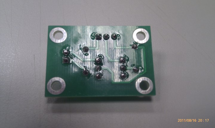
I chance upon Mr.ChongSP’s D&I lab previously. Apart for the SSR kit, I also asked for the Bi-Directional DC motor control kit, which was meant for the PIC18 MCU sets. Thanks Mr.ChongSP! pretty neat huh.
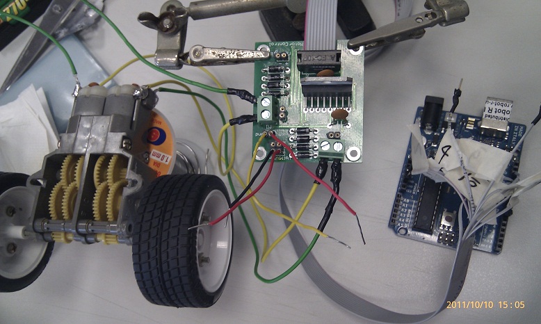
After soldering up the components, it is time to wire up the tamiya DC motors to the motor controller to the arduino. Making the ribbon cable connector break out cable is such a chore and demanding on the eyesight. Luckily I got student junhan to help me on it. Attach the power source. +5v to the motor control (VSS) and >5v for the motors (VS).
Upload the code to Arduino and waiting for the magical moment...... after 2mins... still no sound, no noise and the motor control L298 is totally cool to touch. Something is very wrong here. Check connection, check code, check corresponding pin on motor control board to arduino and to code , just in case there is a mix up. No fault found. A quick check using the Digital Multimeter, only 0.2V measured across the DC motors. Seems to be dry cells I am using the current is not enough to drive the tamiya dc motors. Thus I swap to a 8.4v 200mAh GP rechargeable, only 1 side of the motor is driving. LOLx
A quick swap to conventional DC motors Pheww... it worked
Time to source for some LiPO cells to play with my tamiya motors setup with the Bi-Dir Motor control board!
Currently the DIY PRT prototype uses a HUMANGOUS 24V 10A mechanical relay + transistor circuit to switch between the 5V MCU digital pin and the 24V 10A DC supply to the motors.
In the next step of modularizing the building blocks of the DIY PRT into an Arduino Shield, that AWESOME relay could not fit into the shield. Worst part of it, the EM generated by the motors traversed the wirings and this affect the reading of the sensors. Previously, sparks was observed in the mechanical relay when the circuit turned on while the wheels were locked accidentally. If working in enclosed environment with dangerous gases (not fart pls), the spark might cause an explosion...Worst of it, there is no isolation of high current high voltage circuitry from the low voltage low current MCU. The circuit run a risk of frying the components at the low voltage low current side. Well, unless the opto-isolation circuit (opto-coupler) is included. The circuit get more and more complicated with each additional feature added!
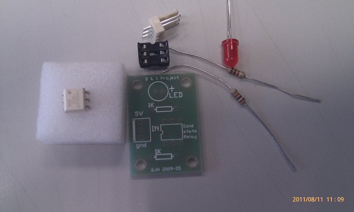
The challenge here is to reduce the size of the relay, have opto-isolation and also simplify the circuit. SSR is here to the rescue~~~ http://en.wikipedia.org/wiki/Solid_state_relay _________________________________________________________________________ One day while running some errands outside the office, I chance upon a SSR circuit from Mr.ChongSP’s D&I lab. It was displayed outside the lab.
Using my thick-skin-jutsu i approached the lab TSO and executed my BBS move on her. Mr.ChongSP and TSO Ms.Jana were more than happy to supply me a set of the SSR kit. thx! Look at the timestamp of the pictures, It took me more than a month to acquire, experiment and write down the experiment. Time is a rare commodity (exam, marking, checking, tallying, data entry, checking again)….If you have some spare CPU cycles, consider to supply me some. The TSO reminded me that this PCB connection is meant for DC-DC switching from low voltage to not so high voltage. But according to the specsheet of the omron SSR (I love omron relays!) http://www.omron.com/ecb/products/pdf/G3VM_351BE.pdf This babe is capable of switching to 280V 100mA !!! Just to be safe, I only try to turn on a LED. lol. A quick peek at the specsheet, this babe is capable of switching DC-DC and also DC-AC depending on the configuration. Soldering the PCB is pretty straight forward with the detail explanation on the silk screen. A point to note, when soldering ICs’ , never mount the IC to the IC holder while soldering the IC holder to the PCB. The heat form the solder might damaged the IC. An advise from my lab TSO many many years back when I was a student here. IMMA such a good student @@” Only plug in the SSR when all the soldering is done.
Pretty neat huh...
Now, connect the GND pin from the PCB to GND pin on Arduino (I found some students make this mistake when wiring up stuffs... The consequences may range from very small such as circuit not working to very serious such as sparks and fried MCU), VCC pin to 5V on Arduino and lastly signal pin to any one of the digital output pins on the arduino.
As for the code, I use the example code found at File->Example->Digital->Blink. The SSR will be triggered at specific interval, turning on the LED. Phew.... everything work at 1st try. Now, time to wire this SSR to more interesting hardware (<10 V load plssss). Interested to play with it ????? dXD