Showing posts with label LED bling. Show all posts

Friday, April 18, 2014

3D printing using NinjaFlex with Makerbot Replicator2 and RepRap Prusa Mendel i3 Durbie v2

3D printing using NinjaFlex with Makerbot Replicator2 and RepRap Prusa Mendel i3 Durbie v2

Earlier in February, yours truly came across an exciting new type of 3D printing filament that is flexible, stretchable, thus allows for many creative creations. Say farewell to the rigidity of PLA and ABS! Without hesitance, yours truly ordered a spool of 1.75mm white filament with a local vendor (probably the first spool brought in here) at SGD100 per pop.
May I present to you, the NinjaFlex by Fennel Drives http://www.fennerdrives.com/ninjaflex3dprinting/_/3d/ .
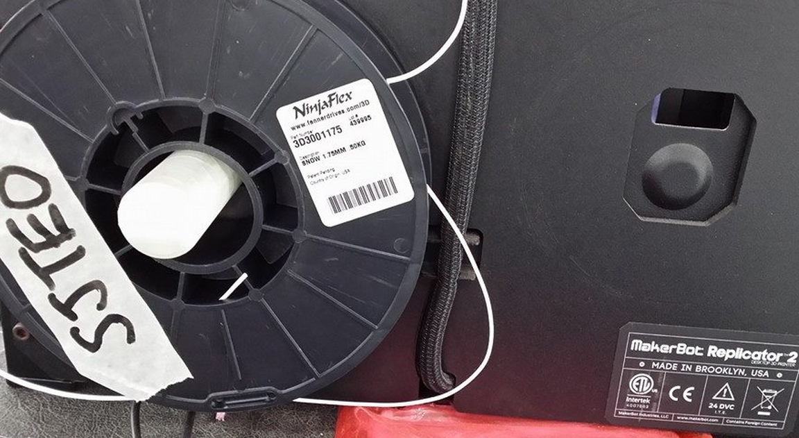
Finally over the last few days, yours truly manage to find some time to play with this excellent new type of filament. Prior to commit, it is best to read the manufacturer’s website and adafruit’s tutorial, and by following the recommended best practices for 3D printing with this NinjaFlex should be a breeze. Technically I summarized from the reading materials, if I followed the recommended extruder temperature of 215degC, non heated bed, and blue tape on the printing bed; it is going to be minimal effort to install the NinjaFlex and we can have a lot of creative fun happening here at FabLab@SP.
Sorry to throw in the wet blanket. The experiment with NinjaFlex is not a breeze, even with the prior knowledge well versed; hence there is a need to raise some awareness and share some experience on how to get it right (or way wrong) with NinjaFlex. Courtesy of FabLab@SP, yours truly has the luxury of tens of makerbot replicator2 at his disposal, and a well-stocked personal arsenal; you guess what, it consist of a 3D printer the RepRap Prusa Mendel i3 Durbie v2
Few important parameters that decide the success rate of 3D printing with NinjaFlex: filament feeder mechanism (FFM), extruder hot end (EHE) temperature, heated printer bed (HPB) temperature, type of tape used on printer bed, and extruder extruding speed (EES). Gathering from the reading material over the Internet, NinjaFlex has a specific operating temperature; users reported success with EHE set at 215 to 225 degC, and HPB set at 30 to 50degC. The filament is flexible and stretchable, sticks well to kapton tape; others reported success on blue tape, scotch tape, and acrylic. However, due to the partiality of info provided by various users that reported success, it is difficult to replicate their success at our end.
Hence yours truly has done several A/B test for NinjaFlex on both makerbot replicator2 and reprap, and varying the parameters.
Experiment1: NinjaFlex 3D printing with Makerbot replicator2 using modified MK2 FFM, non HPB, blue tape on printer bed.
All the makerbot replicator2 in FabLab@SP are modified with spring loaded FFM, as depicted in the picture above. Spring loaded FFM is the must have to print NinjaFlex on makerbot replicator. All parameters such as EHE at 218degC, non HPB, blue-tape on printer bed, EES at 40mm/s are held constant. On first try or maybe it is beginner’s luck, NinjaFlex is loaded successfully, FFM is feeding NinjaFlex with no qualms during loading phase. Next, when it comes to 3D printing with NinjaFlex, the material refuses to stick on the existing printer bed with blue tape, thus excess material clogged the nozzle. Subsequent tries to print, no material is oozing from the nozzle. So, carry out the SOP of unloading the filament, and then clear any material that clog the hot end or drive gear chamber. The next many hours to reload the NinjaFlex are frustrating. First of all, the filament itself is limp, lack the stiffness of PLA, thus it is becoming increasingly difficult to fish the filament through the guide hole. Even though the filament is fished properly through the guide hole, but no material is extruded through the nozzle. The filament is fed continuously in the whole process alright, but somehow, nothing is extruded. Open up the extruder to check for any jammed material at the hole entering the hot end, nothing. So basically the couple of hours are spent on repetitive cycle trying to load the NinjaFlex. The next logical step is to observe ninjaflex filament feeding into the extruder without the heat sink and fan. Surprise!! The filament is winding up in the drive gear. So to conclude this experiment: ninjaflex does not stick to blue tape, filament is too limp to be fed 100% correctly.
Experiment2: NinjaFlex 3D printing with RepRap Prusa Mendel i3 Durbie v2, HPB, kapton tape on printer bed.
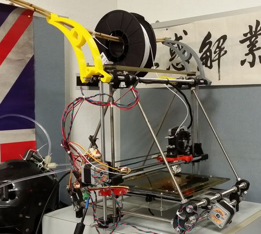
All parameters such as EHE at 218degC, HPB at 40degC, kapton tape on printer bed, EES at 40mm/s are held constant.
Due to the design of the geared extruder, loading the limp filament is a breeze compared to makerbot replicator2. All need to be done basically to loosen the 2 spring loaded screws, manually fish the filament through the guide holes and also into the hot end, tighten the screws and then extrude filament to check for proper feed.
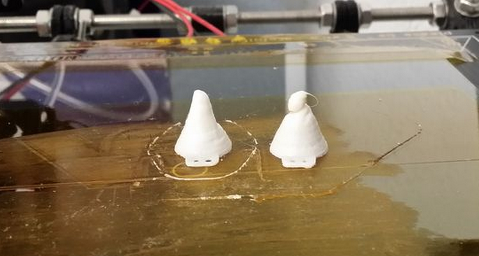
On the first try to print, the ninjaflex did sticks very well indeed to kapton tape. Besides kapton tape, subsequent tries on HPB’s glass plate but without kapton tape sticks well too.
3D Printing win NinjaFlex using RepRap went well. All is left is to fine tune the parameters to achieve the ideal result. Cone on the right is first try, left is second try.
Once the 3D printing parameters are tune with confidence, try it on a bigger print job to check whether 3D printing NinjaFlex with RepRap lives up to it’s reputation. The parameters used are EHE at 220degC, HPB at 40degC, kapton tape on printer bed, EES at 20mm/s. The following parameter is peculiar only to slic3r for ninjaFlex: Fill pattern rectilinear, Infill 50%, 3 shells, 4 skirt loops, layer height 0.2mm,
The first few layers printed according to expectations, however, half way through a 3hour print job of a note3 bumper, the ninjaflex filament is not feeding and starts to air printing. After a few tries with the smaller test prints, apparently the nozzle clogs at random layers and hence air printing too.
While issuing a new test prints, out of sudden the reprap is not printing and pronterface can’t connect to the reprap. First, the ninjaflex is working only to air print randomly, then the reprap stop responding. The experimentation with NinjaFlex on reprap can’t be continued, until the issue with RepRap is resolved. What a bad day to do experiment. The semi conclusion will be NinjaFlex sticks well to kapton (and also glass panel tested before the RepRap went cold), printing with RepRap is a breeze; but need to resolve the air printing.
Experiment3: NinjaFlex 3D printing with Makerbot replicator2 using modified flexMK8 FFM, non HPB, blue tape on half of printer bed, and the other half is clear acrylic.
For experiment1, the suggestion is to find a better spring loaded FFM that ensures 100% chance of feeding the NinjaFlex into the hot end of the extruder. There is ready solution for open source printers, such as the lulzbot flexystruder http://www.lulzbot.com/products/flexystruder-tool-head tailored specifically for NinjaFlex type of filaments. However, not suitable for makerbot replicator2. I guess the good people at fennel drives are serious about their ninjaflex product, reads about the user comment on Internet and thus uploaded a FFM mod http://www.thingiverse.com/thing:169086/
This mod is very easy to install. Simply print out on the existing 3D printer, let it cool by turning off the power supply, and disassemble the existing FFM to be replaced with the flexMK8.
Loading of the NinjaFlex into Makerbot replicator2 could have been easier!!! It takes only a single try to load!
The parameters used are EHE at 220degC, non HPB, EES at 20mm/s. The following parameter is peculiar only to makerware for ninjaFlex: Infill 10%, 2 shells, layer height 0.2mm. As for the test print, see for yourself.
As suspected, NinjaFlex sticks better on clear acrylic than blue tape on printer bed.
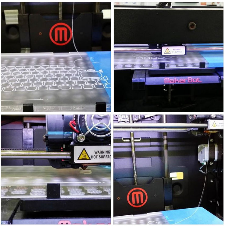
Confidence are built upon many unsuccessful experiments. The first big print job that takes 4 hours to complete with NinjaFlex.
Of course, the experiment with NinjaFlex comes complete with the adafruit cyberpunk spikes
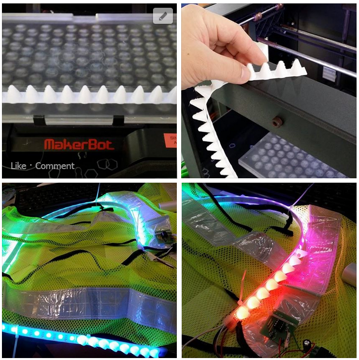

Concluding experiment3: use flexMk8 with makerbot replicator2 for a successful loading, as for the parameters used are EHE at 220degC, non HPB, EES at 20mm/s. The following parameter is peculiar only to makerware for ninjaFlex: Infill 10%, 2 shells, layer height 0.2mm.
Outstanding task: fix the RepRap and then continue to find the best parameter to print NinjaFlex.
References

Saturday, April 12, 2014

\m/ rock on rave helmet for electric run, electro dance music

\m/ rock on rave helmet
Sick of generic off the shelf item for events such as electric run or electro dance music festival????
Make an customized item!
Earlier, I have devised a wirelessly charged RGB LED fiber optic bangle for the missus. She is going to be my pacer, thus when we go for a run and assumed we run close enough to each other, there will be LIGHT.  Just come to realised I have no missus, and the bangle size was not designed for a bloke, I had it shelved. Therefore I devised this helmet specifically for the events above. This rave item is sort of a motivation factor for yours truly the fatty bom bom to flex some muscle besides juicing the grey matter. I am also partially motivated after seeing Natalina’s Fiber optic dress; it is incomplete without a blinking rave head gear of some sort. 

Bills of material
1. Programmable RGB LED light source of some sort using an MCU. I have used my custom PCB for RGB LED to use with ATTiny85. Details of designing the PCB is available here, close up of the assembly of the contraction is available at my earlier instructables.
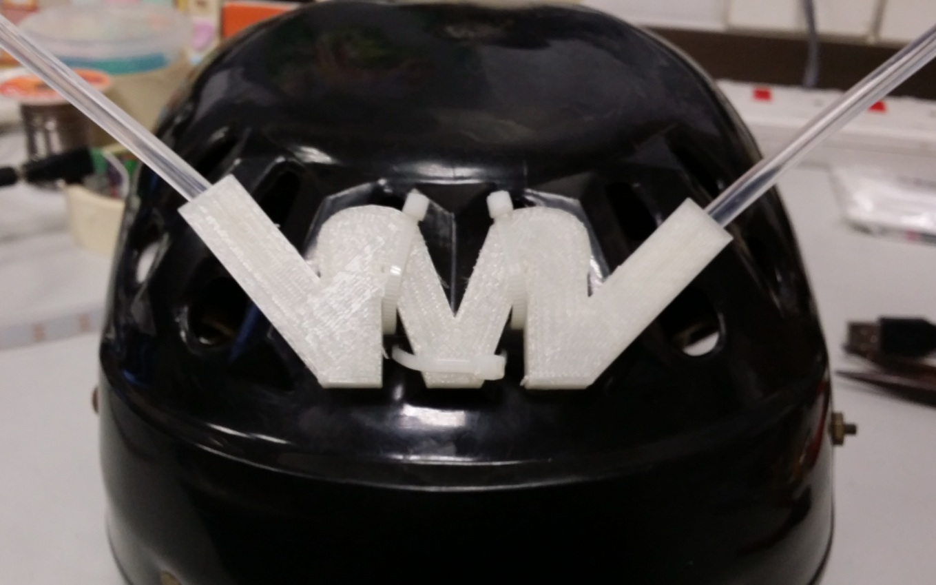
2. Light Diffuser of some sort. I have devised and 3D printed a \m/ rock on insignia in natural PLA with 5% fill and 2shells.
3. Side glow fiber optic cables.
4. Helmet.
Step0
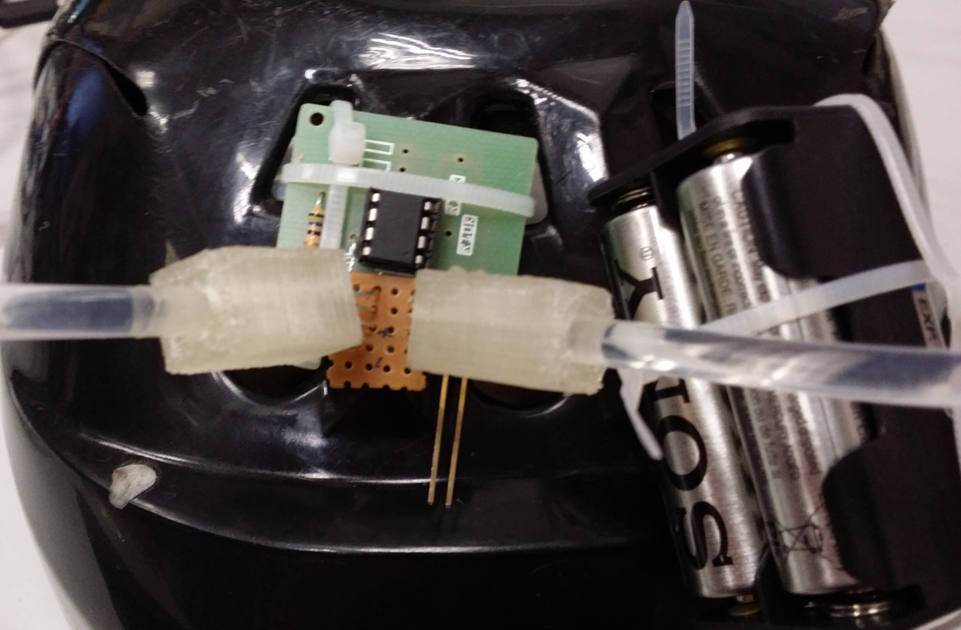
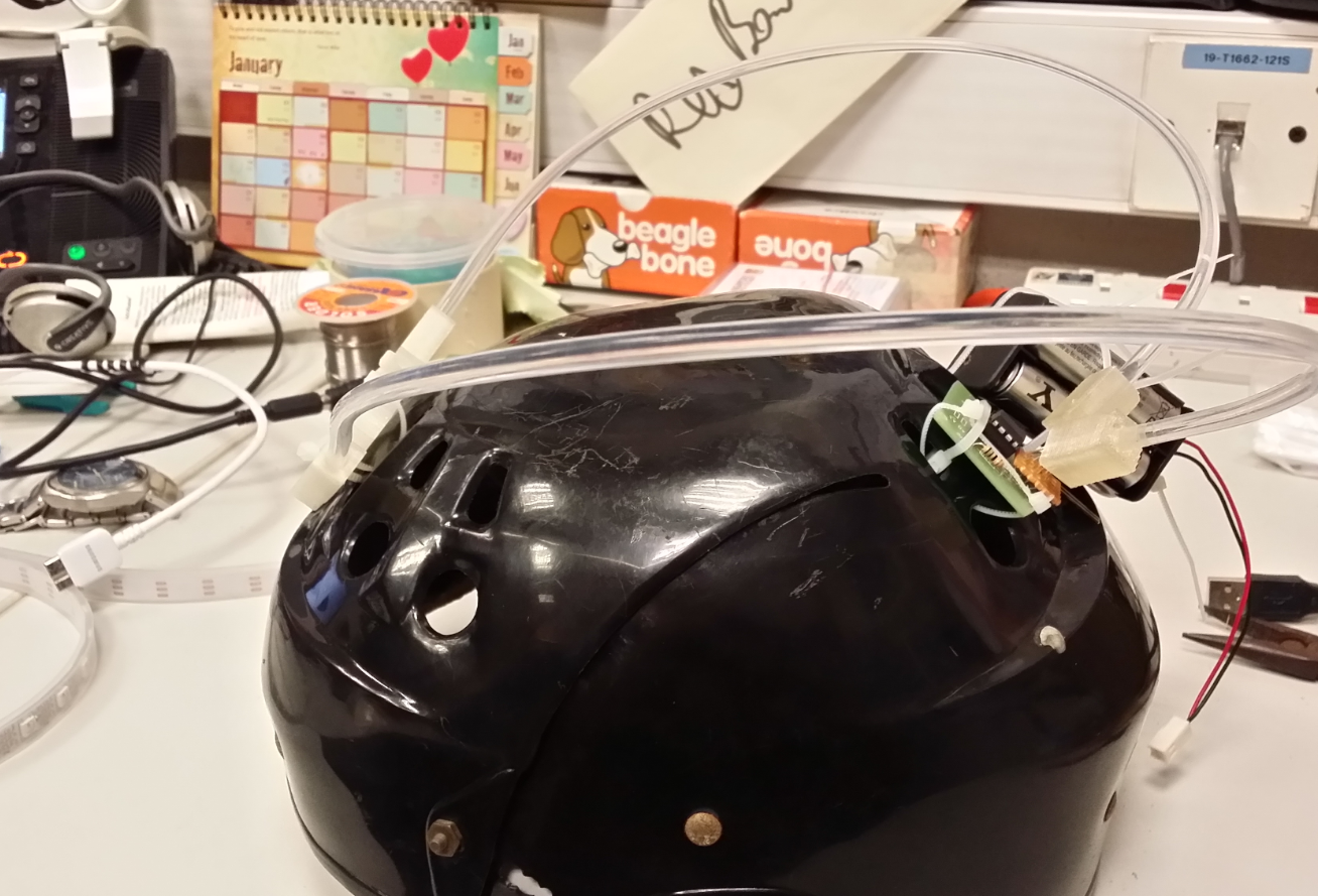
Acquire the components and decide on how to route the fiber optics and measure the length needed. Assemble the programmable RGB LED light source PCB. The final assembly should look something similar to the following pictures. I have some surplus through hole LED diffuser lying around, so I have repurposed them to hold the RGB LEDs.
Step1
3D printed a \m/ rock on insignia in natural PLA with 5% fill and 2shells. The 3D model of \m/ rock on is uploaded to thingiverse. Feel free to download. Assemble the contraption as per the following picture. Insert the 5mm fiber optic cables and it should fit snugly.
Step2
Program the MCU. In this case, it is an ATTiny85.  The public domain RGB LED spectrum fading source code is available here.  
Step3
Fingers crossed. Plug in a 6v supply. Igor, PULL THE SWITCH!!!

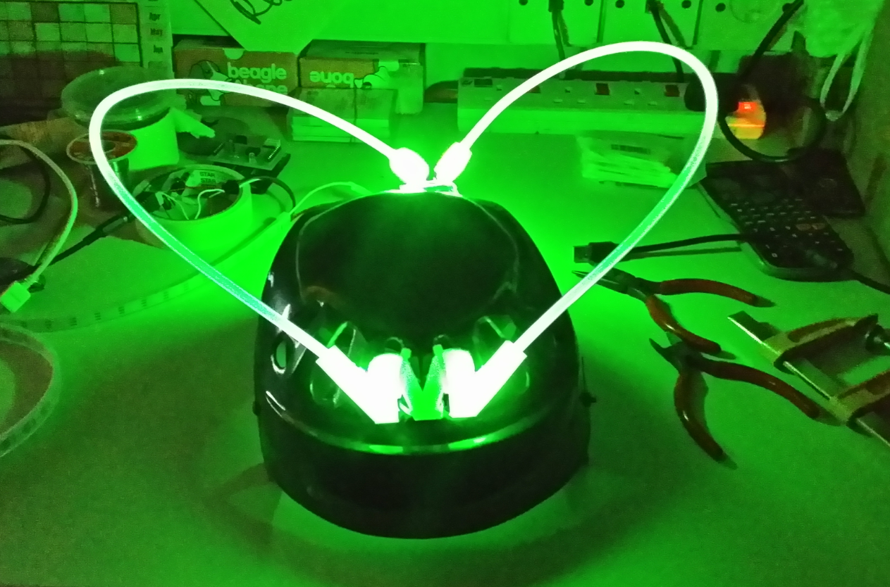
A video will follow later once I find a human willing to wear it. I find it very difficult to take a selfie with my overgrown smart phone while wearing my new contraption.
Wearing my new rave helmet, I was prancing to the venue for electric run but only to realized it is an paid event. I thought it is FREE.... silly me. From public domain info, apparently early birds that book the run enjoy a huge discount as compared to late bird like me that try to sign up late. So, I decide to keep the cash for some Mackey Ds’ and continue to be a fatty bom bom.

Monday, March 3, 2014

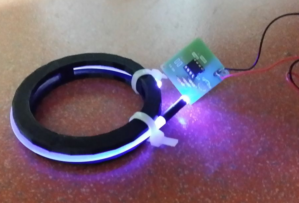
Project you are the ONE. a Wireless powered fiber optic side glow diffused bling

Project you are the ONE. a Wireless powered fiber optic side glow diffused bling
When I was kid, I was fascinated by the world where Tesla and Edison live in. What intrigued me most was the constant debate of AC and DC (at that time), and Tesla’s vision of having power transmitted wirelessly. No cables necessary, no copper mined unnecessarily and friendly to all humans. Wireless power transfers (inductive charging) at that time are pretty much far fetch idea. Nonetheless, the man himself went tirelessly (and possibly drove penniless) to prove his “thing”. Tesla’s destitute demise contrary to Edison’s prosperous life strikes me really hard. I nearly gave up on the dreams to study engineering; thinking I should be a business man or middle man making the in-between of deals.
While growing up, I did get my stab at making a wireless power transfer kit; reading up various recipes from various sources such as text books, “cook books” from BBS etc. , proving the materials read. At that time, I can’t even differentiate the difference between a normal copper wire and enameled wire. Both look the same to me. Without a master to guide in the field of making wireless power transfer (inductive charging) works; many failures afterwards, I came to a conclusion that probably I am better off hitched to my computer (intel 486).
Recently, while doing some read up on “Qi” the inductive power (wireless charging) standard for smartphones, suddenly I realized this might be the perfect time where the inductive charging technology has matured for end users like me to toy on the idea.
I have this idea of making novelty jewelry for the missus: wearable electronics of some sort with wireless power transfer aka inductive charging. The concept story board goes this way: At a seeming random event, I would have a little girl present her with a nicely decorated box that contains the novelty jewelry I made, with a message asking her to “follow the rabbit”. Hopefully the design of the jewelry would be very tempting such that she would put on straight away. Then a rabbit inspired character would walk pass her and hopefully, she would pick up the subtle message of following the rabbit. While following the rabbit, she will come across a few interesting characters that are staged, and the last character to appear will be me. Naturally, we would reach out to each other. Me, being the techie would have the transmitter end of inductive charging well hidden in my hand, and hook up to a ubiquitous disguised mobile power supply that supplies 12V, 1A.
Out of sudden (it is just a matter of time/distance for the EM fields to resonates between the tx loop and the rx loop), her novelty jewelry will light up and the light intensity grew greater as we are moving closer to touch! YESS! You are the one! Both of us will proclaimed. That’s the perfect time for me to take a knee, standby with a unique marriage proposal ring. 

What else? Propose to her!! this engineered piece of art definitely will work. Trust me, I am an engineer.
Oh waittttttttttttttttttttttttttttttttt…………I don’t have a missus/wife/GF yet.
This instructables assumes the following parts.
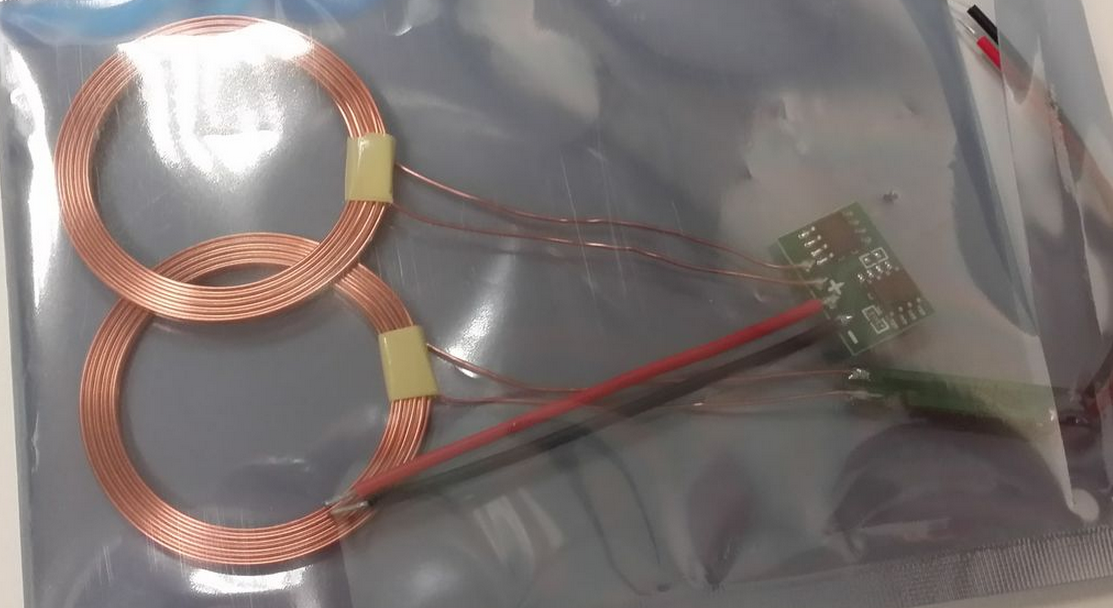
1x wireless charging kit. I got one set that is Chinese made at 13USD from aliexpress.
1x apparatus with RGB LED fading PCB of some sort, which consist of a microcontroller such as Arduino or ATTiny85, a RGB LED and a custom PCB or veroboard. A tutorial to program ATTiny85 with Arduino is available and the necessary ATTiny ISP shield can be made too.
There are many derivatives floating on the Internet. I have used my own recipe of ATTiny85 with RGB. The
step by step guide of “cooking” a PCB of your own is available here.
1x 5mm side glow fiber optic sufficient to cover the perimeter of the wearable apparatus of choice.
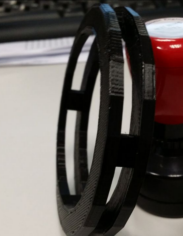
1x 3D printed custom made jewellery to hold the electronics, rx loop, and fiber optic. I have chosen to use a 3D printed bangle. The STL is available here. Print it twice. The two halves are snap fit. It was done in sketchup with the help from xinteng a DCPE yr1.
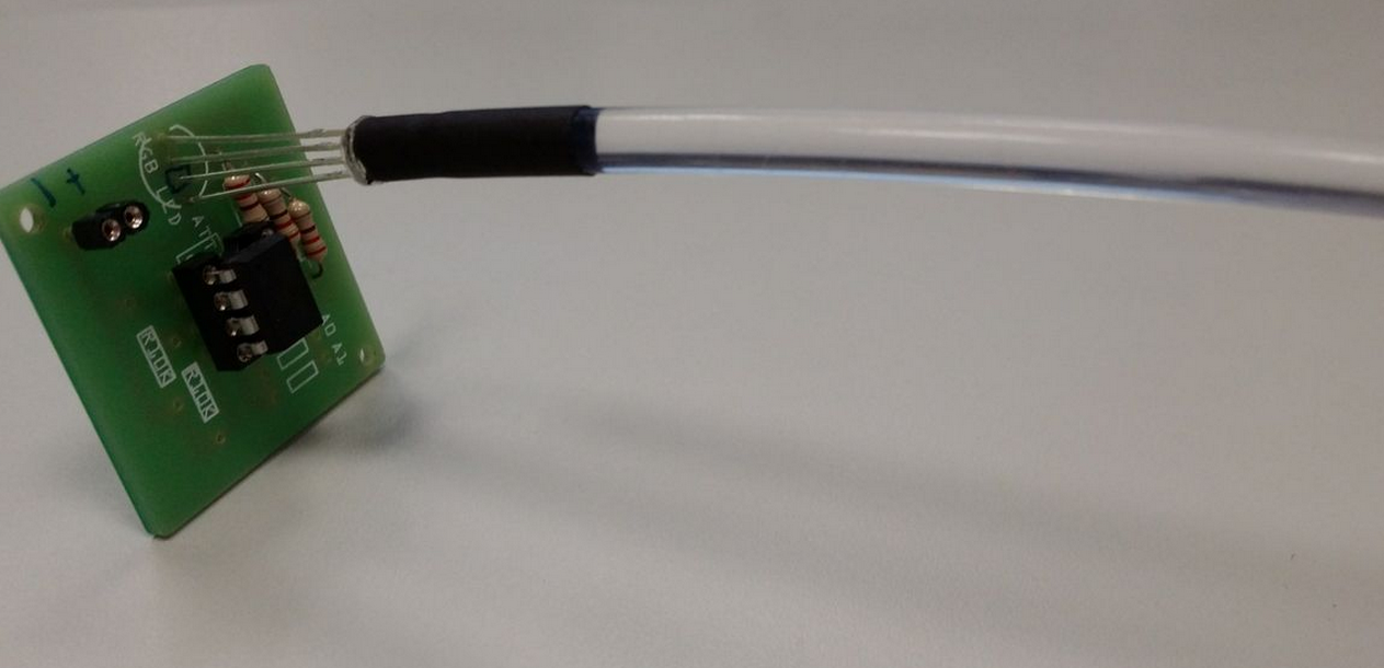
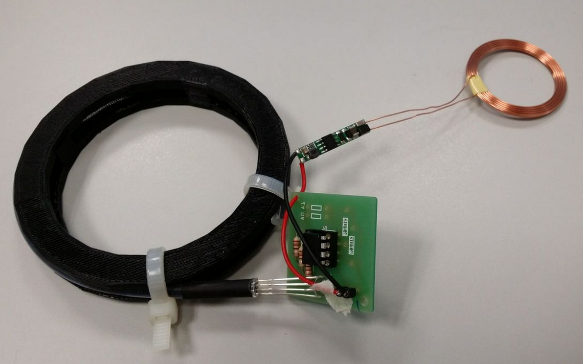
Step1: Assemble the RGB fading PCB, program the ATtiny 85 and mount it onto the PCB. Fiber optic cable is then inserted into a 5mm heat shrink tube. The contraption is then inserted to the 5mm RGB led.
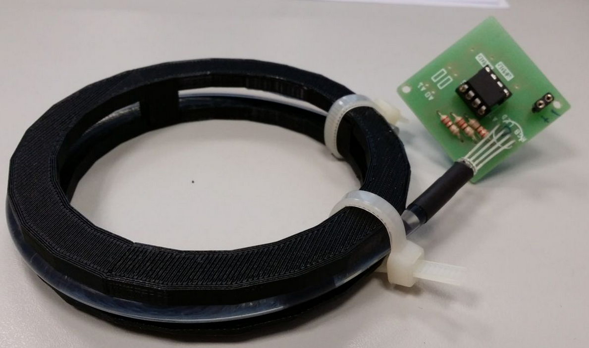
Step2: the assembled contraption in the earlier step is then assembled with the 3D printed bangle. The fiber optic cable are is elastic, and should not be bent at sharp angles. It keep slipping out of the 5mm gap designed to hold it, so I have to resort to cable ties to hold them in place.
Step3: Test the contraption with 3V battery to test for functionality
Step4: Assemble the contraption with the RX induction coil and PCB. I have to resort to use some masking tape to keep the wires in place.
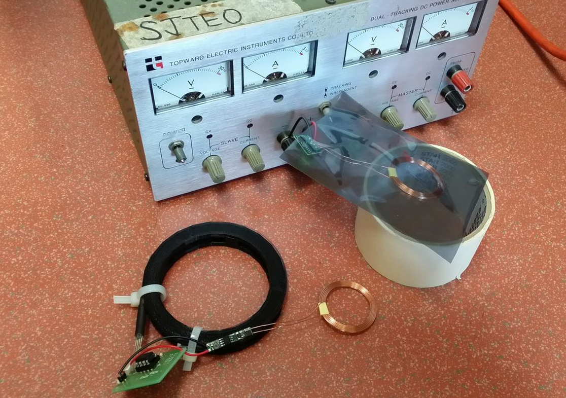
Step5: Test the contraption with TX loop connected to DC power supply. The power supply is set to 12V, 1A.
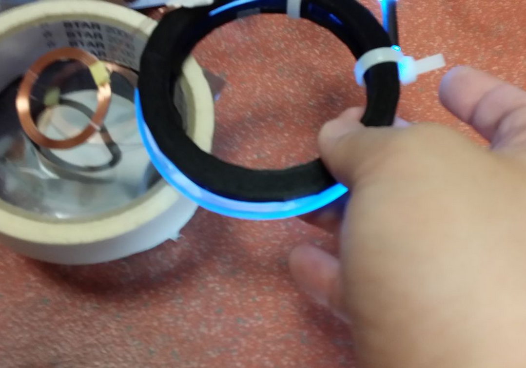
Step5: final check before turning on the DC supply. After turning on the DC supply, observe the behaviour on the EM fields w.r.t to the tx and rx loop. Note: No wireless transfer if the rx and tx loop are orthogonal to each other. The EM fields just cancel each other off.


Look! No batteries needed!

Closeup
here comes the video

Thursday, October 8, 2009

[DIY] Blinking LED bling belt buckle

Last Last week, attended one of my secondary school classmate's wedding. Btw, late Sept and early Oct I have already received 4x invites to wedding. More are in the pipeline..oh my goodnessssssss...........

Arghz, wedding reception is soOOooOoo boring. The food is usually not on par (mass produced), the alcohol is crazy (I'm in the brotherhood team, I'm used to blockade drinks targeting the groom.No drink driving please), lots of photo taking (I don't like to be the subject and I insisted to be photoshopped!!!! RAWRRR)

What totally grab my attention was my the first dish served, the cold platter. The lights are dimmed, Techno song was played (yeay!!!) and at the center of the dish there is this very "beng" blinking LED. It is in the shape of a dome, served in a cup of lightly coloured agar-agar (to give the light a medium to be illuminated). Quickly my I laid my paws on it before my bro daniel get to lay his! haha

Can' wait, I fished out my phone switch on the flash and tried to open the dome. But it is secured by screws! Well, I usually carry a handy tool set with me. No effort at trying to pry it open.

What drove me thinking was, how possible to pack 1 LED, some sort of controller/pic/MCU and battery cell small enough to fit into a dome shaped container at the size of a 20cents????

The content of the dome is just 1 LED and 2 button shaped battery (gives 3v). But, where is the controller???? Upon close inspection of the LED, i saw a tiny weeny black chip in the LED itself. That briefly explains the whole LED blinking sequences. My girl said I am "sua gu" (frog living in a well)...

well....I am pretty much exited with the "new" toy, open it up and find out that I can easily make 1 myself too without the hassle of wiring up a controller/MCU/pic and the considerations to make it small enough to be portable. The sample dome is in my office.

"Inspired" by this blinking LED, I was telling my trainees about this bling i going to make.
It is basically a belt buckle, complete with flashing LED.

Went Sim Lim Square (SLS) and Sim Lim Tower (SLT) last week for window shopping.

What?? Window shopping at SLS and SLT??? Not orchard ION, illuma? you gotta be kidding me!

Was hopping in and out of the shops in SLT looking for cool kit set and wares i can play with.
Chance upon this Flashing LED that cost 50cents each. They came complete default with flashing sequence, such that, there is no need to have a pic/MCU attached to the LEDs. Small is beautiful.

Initially, I only want to use 3v (button sized) to light up the LEDs, so all LEDs are wired in parallel circuit. Because there are too many branches and the current are divided at each branch of the circuit, it is not enough to drive the blinking LEDs. Normal LED are still OK. It Is in the circuit as a referencing point for the "beng-ness", lumens [brightness]. Actually, i only bought 10 of these. "LED not enough lar".

here I gave you my prototype belt buckle, 3v and 9v powered. Can spot the characters I am flashing?