Monday, July 22, 2013

Expensive sensor does matter| DS18B20 with arduino


Last Friday's master class at Institute of Making is Science of Cooking with Dr Rachel Edwards-Stuart; sous vide eggs cooking is part of the itinerary of the workshop. My rig was given a SMALL space next to the supposed "sous vide" cooker (a temperature controlled water bath used in chemistry experiments) loaned from the chemistry department.

Dr.Edwards-Stuart class's is very interesting and technically/scientifically inclined, and she spent some time on explaining the 7W1H of the science of cooking throughout the workshop. The taste of ikura (japanese salmon roe as caviar) with white chocolate still lingers in my mind as I am typing this. weird as it sounds, but the taste is..... We also had an academic discussion on using big data methodology to discover, rank and score top 10 best match of a pair of food items based on their chemical compounds.


We made loads of 63degC eggs as an experiment, using both my setup and the device loaned from chemistry department as an A/B test. Knowing the occasional glitch such as temperature fluctuations, and dc offset on my arduino sous vide with K type thermocouple, I needed some extra pre-cautions to ensure everything worked perfectly. I paced back and forth periodically just to check the temperature of the eggs with a pyrometer just to ensure the temperature is within the tolerate limit for a successful experiment (0.5degC). The process is tiring and defeat the purpose of the computer supposed to make my life easier by automatically monitor, control and adjust the temperature.
Nonetheless, egg carnage was fun.


Stable readings with the new thermo probe.

The iteration before the k-type thermocouple using LM35 worked just fine, until the waterproofed LM35 sensor gave way. My last experiment with the k type thermocouple starts to give me problems. The problems are not the usual peculiarities using a non linear amplifier with a non linear thermocouple; nor the DC offset bias that comes with my al-cheapo amplifier. Rather the values read in are fluctuate wildly, and to make the matter worst, it only fluctuates randomly. There can be a myriad of causes on this issue. A dry joint, capacitance effect, signal noise etc....

So, i have decided to solve my problems once and for all by not being a cheapo and spent a good 5quid inclusive of delivery on a DS18B20 waterproofed temperature sensor.  To compare the prices, LM35 is free from www.ti.com; thermocouple is 2quid. Delivery was prompt and programming was easy with helpful documentations from arduino website.

Just add the 2 libraries needed, import to the arduino sketch and start to write some code. Just a slight note: This sensor is a little bit different from the LM35 or the thermocouple.
With LM35, the temperature value is a matter of arithmetic implemented in code, aka software-ish style
Using the thermocouple, the temperature value is a matter of amplitude amplification by the non linear amplifier, aka hardware-ish style. Whereas with the DS18B20 devices running on the onewire protocol, this allows cascading of multiple sensor devices on the same signal line and best of all each device can be addressed individually. The interesting way of using this sensor is through the API calls available to extract the exact values of the temperature read by the DS18B20 sensor. Truly computer engineering-ish type of implementation.
On a side note, it is not truly plug and play type of sensor. A 5k ohm pull up resistor is required to connect between VCC and data. I was scurrying for one of these 5k ohm in my small collection of resistor but can't find an exact one.  Luckily I have one 20k ohm resistor lying around in my bunch of 330ohm resistor and it works just fine with my 1 sensor setup.
No fluctuations, no wild dc offset, PID is working happily (predictable performance) with the stable values. At last, I had a nice perfect pinkish steak for sunday dinner. Damn, i forgot to take a picture of the steak. I am just too desperate to gobble the steak xD~

Now, the fun part begins!


Sunday, July 14, 2013

hack micro SD card adaptor to low profile for raspberry pi

It has been kind of an eye sore on my raspberry pi, where the SD card adaptor is sticking out of my 3D printed box. Since I am using micro SD card, it should be small enough to fit the SD card slot. The Low-Profile SD to Micro-SD Card Adaptor for Raspberry Pi on amazon cost about 8 quid. I am dead sure I am not going to spend a day's worth of meal allowance on a measly piece of PCB.

So i am going to hack a micro SD card adaptor to low profile, since I have a one lying around with a broken lock (I can't write to my micro sd card with this adapter because of the lock is broken). Warning: this process is irreversible, the modified micro sd card adaptor cannot be returned to its original form. proceed at own cost.

recipe for success: nimble fingers, lots of patience and a stroke of luck.


Carefully fold the pins on the RHS to contact the micro SD card.
Secure both the SD card connectors and micro SD card connectors as necessary.


Conclusion: This hack requires a lot of carefull bending of pins. Theoretically, this hack should work; but it doesn't work on me. I guess I have to secure the microsd to the adaptor one way or the other. 

update: i try another method of folding the pins and also slipping a tiny piece of paper to ensure the contacts are properly connected. it worked intermittenly, pi crumbling at the slightest touch.


For convenience sake, I am buying one of these at 2quid inclusive of shipping. Modify the usb part would yield a long term and stable solution.

Friday, July 12, 2013

Fun with Engduino 2


As mentioned at an earlier post , I am toying on the idea of a signalling bike helmet that uses the the 16 RGB leds with the accelerometer. This idea is dead simple. Tilt the head to the left, light up the LEDs on the LHS, and vice versa for the tilting to the right.

First thing first. Open the Example->Engduino Examples->Acclerometer Example, just to see how the APIs (Application Programming Interface) are used. From my previous experience with 3DOF, 5DOF, ardu pilot IMUs' (Inertial Measurement Unit, usually made up of an accelerometer and a gyroscope), Enduino's is the easiest to use to date. I can write code straight away without worrying too much. The reason, there is no risk of "frying" the IMUs because of a mal-wiring, loose wiring, bad solder joints etc. If the hardware is reliable, troubleshooting the software is much much less daunting.

From the accelerometer example, compile and upload to engduino. open the serial monitor to observe the output. The keything to do here is to stick to one orientation while observing the outputs. I prefer it to hold it "crown side up" . that is looking straight into engduino, the circumference of the board resembles a crown. Now, move the the board on the "x -axis", that is moving the crown horizontally to the plane and observe the output. repeat for "y-axis", that is moving the crown vertically to the plane and finallymoving the crown closer and further to you relatively to the same x and y axis on the plane. The next actions to try out is the roll, pitch and yaw. You cant help but notice that the values of all 3 axis change accordingly.


One thing you will notice that the X Y Z axis values do not correlate to the orientation of crown side up. Here come the interesting bit. As a programmer, if you have decided on the orientation, wrote the code for this orientation but when it comes to mounting but it has to be the other way round, you cant help but notice that your code start to behave erratically. Moral of the story: understand how is the acclerometer is going to be placed before writing code. Of course some may argue to stick to the "original" x y z axis of the board irregardless of the application and write code that corresponds to this. Both methods are do-able, there are more than one way to skin a cat.


The code/theory to track the changes of the x y z axis values as close as possible can be a little bit to over stretched in this post. Each of the topics such as smoothing technique, PID, 3D kalman filter and etc deserves at the minimum a chapter each in the classic control theory book. Nonetheless, it is just a google away to learn more!

My toy that is held with crown side up, the value of the "y-axis" changes in the range of +- 0.1 when I tilt it left<->right. So I am going to exploit this "behaviour" and tailor my code surrounding it.

Check out the video below to see it in action!


here comes the code


Just in case you wonder what an arduino + IMU + control theory can do, check out my previous toy

Thursday, July 11, 2013

FUN with Engduino


Engduino is an arduino with loads of bells and whistles (16 RGB LED with corresponding LED drivers, accelerometer, thermistor, IR receiver, LiPO battery) assembled together for some really serious fun with programming. Engduino was developed with a philosophy in mind. It is meant as a teaching tool for school children visiting UCL, to embrace programming.


IMHO, most new adopters of arduino that want to jump straight to code development often found them self in a situation where hardware components are hard to come by; either it is too time consuming or simply too expensive to acquire the necessary I/O parts. If I am getting a barebone arduino and stackable sensor shields that are the equivalent to engduino's sensors, I think I would have to survive on free coffee and leftovers from conferences held in campus for the rest of the month. Courtesy of Prof.Hailes, now I am a proud owner of Engduino #073.

Engduino comes with a clear cut instructions on installing for windows, mac or linux and also well documented API to leverage on the available hardware. Existing arduino users might want to download the entire engduino libraries packaged with arduino IDE from ehre. Just download it and unrar the content to a folder (other than the existing arduino folder if you already have one), install the corresponding drivers for lilypadUSB, and click on arduino.exe in the folder you have just unrar to get started. I strongly recommend to take a look at the existing examples->Engduino to understand how to use the API.

The only thing I like about programming on a computer is, I can experiment with code and not fearing the computer will explode. I have seen enough segfaults and core dumps but nobody was hurt. Having said that, programming without understanding the underlying "computer parts" can result in devastating effect and cost lives. With great ability comes great responsibility.

So...... with your newly acquired programming skills and also ownership of an engduino, what can be done?

For starter, check out my re-mod version of the persistence of vision (POV) toy I had some years back. my original POV toy calls for 8LEDs in a column, but the engduino have a maximum of 5. So, I have done some cheat mod in code by limiting the characters to 5LEDs in the same column. Hopefully, the output will turn out well in testng.


When I was about to test my new toy, I only came to realized that I do not have a USB extension cable long enough for me demo and also record a video of the POV in action. I will upload a video of engduino in action once i get my paws on the usb cable.

So whats next fun thing to do with Engduino??? I am toying on the idea of a signalling bike helmet that uses the the 16 RGB leds with the accelerometer.

POV code below


 As promised, here comes the video. I have to admit it is kind of difficult trying to video this POV ala selfie.

vmware ubuntu kernel panic

I got a shocked this afternoon when the machine where most of my work is residing decides to kernel panic.

As usual, I turn on my ubuntu vm in vmware to do some code development and only to be greeted by a flashing or blinking caps lock led on my laptop. my keyboard and mouse input froze the moment i click within the vm. Flashing LEDs on a keyboard of a linux machine is an indicator of kernel panic. it is so weird, because I was still using it yesterday.

Pressure and suspense start to build as time pass. If this machine failed me, my setup for development work will be gone and I need to spend time to rebuild it. After spending several hours online desperately looking for a solution to my ubuntu machine's kernel panic, but none works.

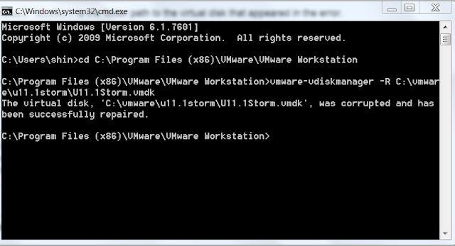
I made several speculations about why it kernel panic, but none of my assertions were correct. Assertions such as I need to recompile the kernel, some important sys files are deleted accidentally, HDD saturated with junk, etc. Only when I want to expand the hdd space manually via gparted, than i saw the error message the vmdk is corrupted. Suddenly I recalled that in the morning, my windows7 host machine booted into a chkdsk screen scanning and fixing the hdd for errors.

jackpot. it is easy if you know what you are solving for.

I present to you the command that saves the day (and also my blood, sweat and tears for the last couple of weeks). after this command is entered, I can defrag the vm hdd which means the fix is successful.


Monday, July 1, 2013

New toys in town! Makebot replicator 2X

look at the bad boys, now with ABS!!


some 3D printing fun


quick and dirty way wiring a K type thermocouple with LM358 op amp to replace LM35 on an Arduino

Personally, I prefer to use LM35 as my temperature sensor instead of anything else. The reason is simple, it is bountifully available in our tech arsenal (just a mouse click and I can collect it from block T8), it is very simple to use with no extra circuitry, precision at +- 0.5degC within 0degC to 100degC, and literary it is plug and play with arduino. check out my previous post  on getting started with LM35 and arduino. I am using this sensor for my arduino sousvide setup. After 6 months of abuse, it broke down, the waterproof temperature probe gave way, and water breached in it causing a short circuit. Shown below is my wiring for LM35; the optional 10K Resistor is there to suppress wiring capacitance that came with very long cables.


so my next course of resolution would be to get my hands on spare LM35, and also another method to water proof it. Little did I realise, a small little piece of LM35 is retailing at £1.99 per piece!  To add salt to the wound, a pathetically sized 6cm x 4cm veroboard (stripboard) cost me £1.69 after 50% discount. The price gave me a real shock in my life. I always assumed that ICs are dirt cheap. The other possible explanation is that I have been living in the tech tower with a wide variety of ICs, PCBs, EE components at my disposable to make projects, losing touch with the reality. Arghhhh, how i miss my staffs at the procurement office. Not because of the complicated purchasing process I constantly bang into, but their effort to make sure we are well stocked.

After much googling around and also posting messages on my facebook to BBS (beg borrow steal). I came across websites such as TI are giving samples for free. Since I am staying across the pond and have an expensive looking email address, I can get my hands on 3 type of ICs with 3 samples of each in an order for free, and with shipping included too. As a backup plan, I also ordered a some ICs to complement my K type thermocouple that I have ordered earlier on amazon for £2.93 with free shipping.


The plan is simple. Solder a LM35, stick it into a brass radiator key I have idling around, and seal it with sugru. Sugru is going for £8 per packet of 5 mini sachets. I only needed one. My prior experience  with sugru is a wasteful one. It has an expiry date that will be cured (harden) by than no matter what. Nonetheless, it is a good material to fix stuff. I posted a message on facebook group seeking partners to share the cost of materials; a kind soul from institute of making gave me 2 mini sachets for free!


Always test your equipment/stuff before sealing/cast in sugru or committing more materials on top of the equipment. In my case, i tested this waterproofed LM35 on my arduino before cooking an expensive piece of dry age beef. To my amusement, the temperature reading is fluctuating wildly. This is really bad signal to be the input for the PID control algorithm. It makes the tracking to the set point difficult and unreliable. To make the matter worst, the sealing of the edges on the brass radiator key with sugru did not went well as expected. When it is submerged in the water bath, I saw some air bubbles emerging from the thermo probe.

There can be a myriad of ways on what went wrong. leaky probe, faulty LM35, wiring capacitance that affects the reading, faulty pin on arduino etc etc. Thus, the great troubleshooting begins! I started off plug and play with another LM35 I soldered, but used a plastic bag instead for water proofing. Still the same old wildly fluctuating reading. After much troubleshooting and have exhausted all possible options, I tested the last piece of LM35 before solder and after solder. Ah-ha.... found the culprit. The solder iron is too hot for soldering ICs, and I have put it in contact with LM35 for too long a second.

Having busted 2 out of 3 of my LM35 and lost the 3rd in translation, I am back to my K type thermocouple. One reason that make me don't really like to use K type for my sousvide setup, is because it's temperature range is very wide, it is ranging from -260degC to 1400degC (manufacturer dependent). Divide the temperature range with 5v and than you will get what I mean. Reasons not listed exhaustively for my dislike include the requirement of a cold point compensation circuit for precision; signal output is in the range of milivolts per degC; it need an amplifier circuit to work, and can't connect directly to arduino; the amplification is not exactly linear for a cheapo amplifier which makes the code complicated to work with the circuitry; adafruit Thermocouple Amplifier MAX31855 breakout board going to cost me £16.80 from a UK dealer; and the list goes on.

Having said that, a very simple op-amp with a gain in the range of 100 would easily fit the bill for my setup with K type thermocouple. I just need to figure out the output voltage in milivolts of my k type thermocouple would output at the desired temperature for cooking, amplify it and normalized it to the temperature in degC. The first step is a re-visit to the data sheet of a LM358 IC, something I have not done for some time. To be frank, these ICs data sheets are not written for the layman in mind. Reading the data sheet not knowing what you need or a how to get things done will surely put off many people and abandon the project (not as if their livelihood depends on it). Scrutinizing the data sheet in detail, I just wonder why it does not include the classic text book example of a N-gain amplifier. I forsee that layman looking for something quick and fast through the data sheet will be disapointed and will spent hours trawling the internet for usable bits of info. How many will give up half way or abandon their project in due course of looking up for information?

The quick and dirty way of wiring of LM358 is at the self explanatory figure below, drawn by hand from yours truly.


B-side of the £1.69 veroboard. I still remember what was taught in my digital electronics class many years back. The hint is in the picture below.


Putting everything together for action. no smoke, no sparks. phewwww


I noticed the reading of the k type thermo couple from the LCD with comparison to my trusty digital thermometer. The final temperature read by K type thermocouple with LM358 is always biased at about 9 to 10 degC. This render the previous code useless. Nonetheless, it is easy to fix.

The only modification to the source code, from the code meant for
LM35-> temperature = (5.0*val*100/1024);
 is modified to
LM358-> temperature = (val+9.5);

ARGHHHHH.... can you smell what the ROXXX is cooking?!