[youtube]C9wnJz-ZPrA[/youtube]
1. gently pry at the sides of the WD passport essential 2.5".
1.1 Use your fingernail/screw driver/card
2. gently lever at the rounded edge, one side at a time
3. pull out the white colour plastic piece gently.
4. Remove the shock absorbers (4pcs total)
5. gently slide the 2.5" hdd out of the aluminium housing
6. There you have a 2.5" WD 500GB hdd. HDD alone retails at s$138 at SLS, comex is selling at $119 for wd passport essential 2.5" 500GB
Monday, September 14, 2009

Monday, August 3, 2009
[DSA] Feed back~~~
Feedback about me, my style, what have you learned from me. Not forgetting what you want me to improve on for the lessons conducted. Btw, slimming is not one of the expected answer from you.
Wednesday, June 17, 2009
[DIY] 3x3x3 LED cube
Saw some really cool 3x3 led cube. It might just be the "it" decoration for my office to make it a more disco-ish setting. Grab some LEDs and components from the store and lets get cracking. My apologies for the late posting, was rather caught up recently.
The design concept I wanted is the cube got to be detachable. So any time I am bored with the colours, or I got my hands on some RGB LEDs, min effort is needed to mod the LED cube. If every thing is soldered down, there is not much flexibility. Thus, I gotta make another cube. I did have something that is pluggable, upgradeable and easy to modify.
time: 2 Hr (fashion the cube and soldering) 2Hr(making of vectorboard, jumper wires to MCU), programming the MCU (timeless)
To make fashioning of the cube easy. I made 9 holes on the cover of a paper box. This will make the bending of the LED pins easy. Make sure you align the cathode and anode accordingly. We will be folding the cathode together.


This will what you will have after fashioning 3 layers of 3x3 LEDs.

About the detachable design, it was excuse for me not to solder it. I don't really like to do soldering job. The fumes just make me nauseous. So, I used some PCB jumpers. This are commonly seen on HDD and CD roms / DVD roms to select the master / slave mode. There go the frenzy to look for OLD hdds and optical drives to salvage those jumpers. Later, because of the use of PCB jumpers, some problem occurred which I will elaborate later.


Solder the layers on a vector board or strip board. Your choice. Make room for the jumper pins. Here I choose to light up a layer by pulling the cathode to ground and the individual Led by the 3x 3pins to high. The trick here is to pull an optical illusion on the viewer. Human vision will not notice flicker that is above 100Hz. Moving pictures of 27 frames per seconds make it a video. We shall use this concept when programming. Hence each layer are light up with a certain combination at a certain "refresh rate" to create the illusion of moving/running lights pattern.


Hook up the led cube to the MCU. I am using a PIC16F4220F out of convenience. It is the only available MCU on my desk. you can use ARM, other PIC etc.

Before all the programming rush, we need to ensure all the LEDs are working properly. A diagnostic sequence need to be run by simply light up all the LED. For my cube, not all LED light up accordingly. When I move the individual LEDs slightly, they light up and dimmed. Intermittent lighting is not what we wanted. The problem might derived from the design that uses PCB jumpers instead of solder everything.


Now, in a split for a decision. Should it be soldered, loose the ability to be modify easily or find another method to achieve the hack-ability.
Akan Datang....................
Interested to continue where I left? Buzz me.
The design concept I wanted is the cube got to be detachable. So any time I am bored with the colours, or I got my hands on some RGB LEDs, min effort is needed to mod the LED cube. If every thing is soldered down, there is not much flexibility. Thus, I gotta make another cube. I did have something that is pluggable, upgradeable and easy to modify.
time: 2 Hr (fashion the cube and soldering) 2Hr(making of vectorboard, jumper wires to MCU), programming the MCU (timeless)
To make fashioning of the cube easy. I made 9 holes on the cover of a paper box. This will make the bending of the LED pins easy. Make sure you align the cathode and anode accordingly. We will be folding the cathode together.


This will what you will have after fashioning 3 layers of 3x3 LEDs.

About the detachable design, it was excuse for me not to solder it. I don't really like to do soldering job. The fumes just make me nauseous. So, I used some PCB jumpers. This are commonly seen on HDD and CD roms / DVD roms to select the master / slave mode. There go the frenzy to look for OLD hdds and optical drives to salvage those jumpers. Later, because of the use of PCB jumpers, some problem occurred which I will elaborate later.


Solder the layers on a vector board or strip board. Your choice. Make room for the jumper pins. Here I choose to light up a layer by pulling the cathode to ground and the individual Led by the 3x 3pins to high. The trick here is to pull an optical illusion on the viewer. Human vision will not notice flicker that is above 100Hz. Moving pictures of 27 frames per seconds make it a video. We shall use this concept when programming. Hence each layer are light up with a certain combination at a certain "refresh rate" to create the illusion of moving/running lights pattern.


Hook up the led cube to the MCU. I am using a PIC16F4220F out of convenience. It is the only available MCU on my desk. you can use ARM, other PIC etc.

Before all the programming rush, we need to ensure all the LEDs are working properly. A diagnostic sequence need to be run by simply light up all the LED. For my cube, not all LED light up accordingly. When I move the individual LEDs slightly, they light up and dimmed. Intermittent lighting is not what we wanted. The problem might derived from the design that uses PCB jumpers instead of solder everything.


Now, in a split for a decision. Should it be soldered, loose the ability to be modify easily or find another method to achieve the hack-ability.
Akan Datang....................
Interested to continue where I left? Buzz me.
Wednesday, May 20, 2009
[DIY] Breath New life in OLD laptop
mod time: 10min (mount the CF to 2.5" IDE reader) + 120min (tryin to fix windows NTLDR missing problem) + 30min (install Fedora 10 + yum to install software)
Mod gears: CF to 2.5: IDE reader= $18, Kingston elite pro 133x 8GB CF =$32. total $50
Siti got me a compaq laptop evo N1000v
which is in a semi paralyzed state with a broken/faulty HDD and intermittent screen flicker under windows XP.

So why throw away??? Since we can use it do do a lil bit of experiment, modding and hacks. Hey, if it is destined to be browned during the experiment, it is still trash. We are tryin to turn trash into something useful here.
Again, why CF? First of all, it is easily available, consume less power and voltage compared relatively to a 5400rpm 2.5" IDE hdd. Shock proof, you can jump up and low with the new mod. And hopefully, the battery life will improve. It is after all a OLD laptop, using p4 2.0Ghz, 512Mb DDR1 ram.
locate where the HDD is secured at the base of the laptop. Different make laptop have different orientation.

take out the battery pack. I do not want to accidentally turn on the laptop when I am modding it.

tough luck. The screw is of a crown shape instead of the more generally available phillips or flat type. Anyway, it can still be opened by a flat type screwdriver. You just need to get the ideal size. Worst case scenario, pour some super glue into the crown, attach a phillips type screw on it. Wait to dry. Then unscrew~

take out the hdd


The CF card reader i got from sim lim square did not clearly mark which is pin 1. So I have a 50-50 chance of frying my newly minted 8GB CF card and the laptop connector (which i never will teeheehee :). Anyway, the best guess you can make is to align the CF reader and the HDD to check out what is the orientation for the laptop. You do know which is the pin 1 on a CF card.

this is how it looks like when plugged in. Caution: It might look different on your laptop because of the hdd orientation is different among laptop brands.


Install winXP. standard operating procedure. During install process, it need to reboot then I encountered missing NTLDR and the computer refuses to start. Spent a good 2 hours troubleshooting (recovery console, copy missing file manually etc) but to no avail. If you know some tricks to fix which I do not, leave me a note.


sick of it. I am going to install my fedora 10


to cut the long story short. Below are the screen shots.

Finally installed


Some baseline bench mark need to be done. Items to check
-battery life before and after mod. best is to play a movie with full brightness and full sound. both from the disk and cd.
-disk access rate with HDTUNE
etc.
I am pressed for time. If you could share the benchmarks and baseline data with me, I am more than happy~ :o)
NOTE: CF cards have a known read/write cycle and MTBF (Mean Time Between Failure). Do check it out before plunging your precious dollar into this mod.
attached is the youtube video. Sorry for the poor quality and only BG noise. I am OMO.
akan datang, to be continued....
fancy SDHC boot on sata for your laptop that uses sata HDD?
looking forward to get my paws on these ACARD ANS9012!!!

too bad their local distro listed here does not have it in singapore...grzzz
http://www.acard.com.tw/english/fd0201.jsp?area=Asia
the closest i can get locally is from vr-forum. too bad it is sold.
Not sure whether it is the only piece of singapore.
http://forums.vr-zone.com/singapore-marketplace-garage-sales/351800-wts-acard-ans-9012-can-take-6-x-sdhc-s-80-a.html
can't wait for my kaki jialing to get it from taiwan....hope the price will be affordable enough. TCO of the connector + 6x8GB SDHC shld not exceed the price of the current same capacity price. If not, it defeat the purpose of modding.
http://www.oc.com.tw/article/0807/readarticle.asp?id=6478#1
update: went SLS storage studio for this SDHC to sata 2.5" card. The shop keeper quoted me $130. Which means, if I want to get 6x 8gb SDHC (48GB) to boot my laptop my TCO will be
$130+ $30x6 = $210. The price is kinda steep. Shall find out prices on SSD during the june PC show before I dive in.
Mod gears: CF to 2.5: IDE reader= $18, Kingston elite pro 133x 8GB CF =$32. total $50
Siti got me a compaq laptop evo N1000v

which is in a semi paralyzed state with a broken/faulty HDD and intermittent screen flicker under windows XP.

So why throw away??? Since we can use it do do a lil bit of experiment, modding and hacks. Hey, if it is destined to be browned during the experiment, it is still trash. We are tryin to turn trash into something useful here.
Again, why CF? First of all, it is easily available, consume less power and voltage compared relatively to a 5400rpm 2.5" IDE hdd. Shock proof, you can jump up and low with the new mod. And hopefully, the battery life will improve. It is after all a OLD laptop, using p4 2.0Ghz, 512Mb DDR1 ram.
locate where the HDD is secured at the base of the laptop. Different make laptop have different orientation.

take out the battery pack. I do not want to accidentally turn on the laptop when I am modding it.

tough luck. The screw is of a crown shape instead of the more generally available phillips or flat type. Anyway, it can still be opened by a flat type screwdriver. You just need to get the ideal size. Worst case scenario, pour some super glue into the crown, attach a phillips type screw on it. Wait to dry. Then unscrew~

take out the hdd


The CF card reader i got from sim lim square did not clearly mark which is pin 1. So I have a 50-50 chance of frying my newly minted 8GB CF card and the laptop connector (which i never will teeheehee :). Anyway, the best guess you can make is to align the CF reader and the HDD to check out what is the orientation for the laptop. You do know which is the pin 1 on a CF card.

this is how it looks like when plugged in. Caution: It might look different on your laptop because of the hdd orientation is different among laptop brands.


Install winXP. standard operating procedure. During install process, it need to reboot then I encountered missing NTLDR and the computer refuses to start. Spent a good 2 hours troubleshooting (recovery console, copy missing file manually etc) but to no avail. If you know some tricks to fix which I do not, leave me a note.


sick of it. I am going to install my fedora 10


to cut the long story short. Below are the screen shots.

Finally installed


Some baseline bench mark need to be done. Items to check
-battery life before and after mod. best is to play a movie with full brightness and full sound. both from the disk and cd.
-disk access rate with HDTUNE
etc.
I am pressed for time. If you could share the benchmarks and baseline data with me, I am more than happy~ :o)
NOTE: CF cards have a known read/write cycle and MTBF (Mean Time Between Failure). Do check it out before plunging your precious dollar into this mod.
attached is the youtube video. Sorry for the poor quality and only BG noise. I am OMO.
akan datang, to be continued....
fancy SDHC boot on sata for your laptop that uses sata HDD?
looking forward to get my paws on these ACARD ANS9012!!!
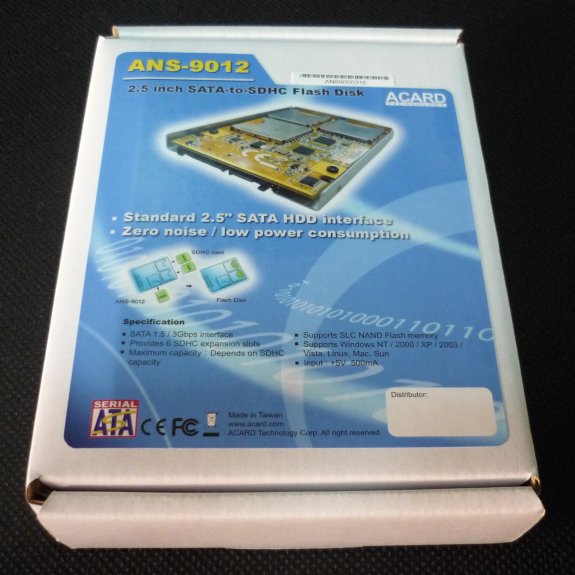
too bad their local distro listed here does not have it in singapore...grzzz
http://www.acard.com.tw/english/fd0201.jsp?area=Asia
the closest i can get locally is from vr-forum. too bad it is sold.
Not sure whether it is the only piece of singapore.
http://forums.vr-zone.com/singapore-marketplace-garage-sales/351800-wts-acard-ans-9012-can-take-6-x-sdhc-s-80-a.html
can't wait for my kaki jialing to get it from taiwan....hope the price will be affordable enough. TCO of the connector + 6x8GB SDHC shld not exceed the price of the current same capacity price. If not, it defeat the purpose of modding.
http://www.oc.com.tw/article/0807/readarticle.asp?id=6478#1
update: went SLS storage studio for this SDHC to sata 2.5" card. The shop keeper quoted me $130. Which means, if I want to get 6x 8gb SDHC (48GB) to boot my laptop my TCO will be
$130+ $30x6 = $210. The price is kinda steep. Shall find out prices on SSD during the june PC show before I dive in.
Monday, May 4, 2009
[DIY] emergency HP charger
was telling one of my student about this DIY and he thought I am not being serious.
below is the excerpt of the email exchanges.
mod cost=$0 (Usable and decommissioned HP and HP charger)
mod time=5minutes

This is my sony ericsson HP charger, It is OLD, but still in working condition. Anyway, for the sake of completing this mod, I shall use it anyway.
The rating of the charger for output (The data that concerned us) is 4.9V and 450mA. My 2x 1.5v battery pack is seriously under powered.

Stripped off the insulators. I am in luck, there are no proprietary colours or wires inside the cable. Red is +ve, Black is -ve. Please be very sure when hook up to the voltage source. The charging is unforgiving for wrong polarity.

Charge baby charge!!!!! Sorry for the ill taken picture. I need to hold the connections with my left and take the picture with my phone on my right. Wait, what phone??? My work/play/study/IM/web phone.
IT WORKS!!!!!!!!!! RAWR!!!
Here is the youtube video. Sorry for the ill taken video, I am OMO (One Man Operation)
below is the excerpt of the email exchanges.
mod cost=$0 (Usable and decommissioned HP and HP charger)
mod time=5minutes
The Mod I am referring to is for your phone.

1. Find an unused/spoilt charger for your phone. Snapped the wire and keep the side which connects to ur hp.
2. Find out what is the pin out (eg GND, +5, data etc) of the connector, and also the voltage range (should not exceed 6v)
3. find some AA batt, hook in series to get 3v or parallel to get 1.5v but longer time, wire the + to +5v and - to gnd.
4. Fingers crossed, hope your phone will not get fried.

try at your own risk horrrrrrrrrr

This is my sony ericsson HP charger, It is OLD, but still in working condition. Anyway, for the sake of completing this mod, I shall use it anyway.
The rating of the charger for output (The data that concerned us) is 4.9V and 450mA. My 2x 1.5v battery pack is seriously under powered.

Stripped off the insulators. I am in luck, there are no proprietary colours or wires inside the cable. Red is +ve, Black is -ve. Please be very sure when hook up to the voltage source. The charging is unforgiving for wrong polarity.

Charge baby charge!!!!! Sorry for the ill taken picture. I need to hold the connections with my left and take the picture with my phone on my right. Wait, what phone??? My work/play/study/IM/web phone.
IT WORKS!!!!!!!!!! RAWR!!!
Here is the youtube video. Sorry for the ill taken video, I am OMO (One Man Operation)
Subscribe to:
Posts (Atom)