Wednesday, November 18, 2009

[warez] poor man's projector


Poor Man's Projector for Entertainment.

 I was toying with the idea of owning a projector at my pad. So that I can watch movie, play games, do word processing, write code on the BIG screen. It's year end nearing the corner and this is the time where all the "crazy" sales begin. But The projector's price still as "crazy". Ranging from s$1k and above for a XVGA ones with acceptable lifetime of the bulb. I should save my year end bonus for paying the education loan i have taken and pay for more important stuffs (buying a LV neverfull is never important! duh...), instead of splurging on warez.

  I am not going through the details about LCD technology, but here is where you can read more about it. http://en.wikipedia.org/wiki/Liquid_crystal_display. I love wikipedia!

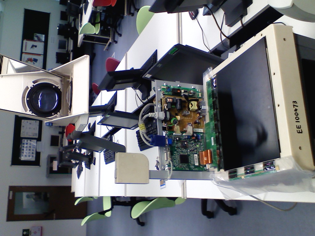
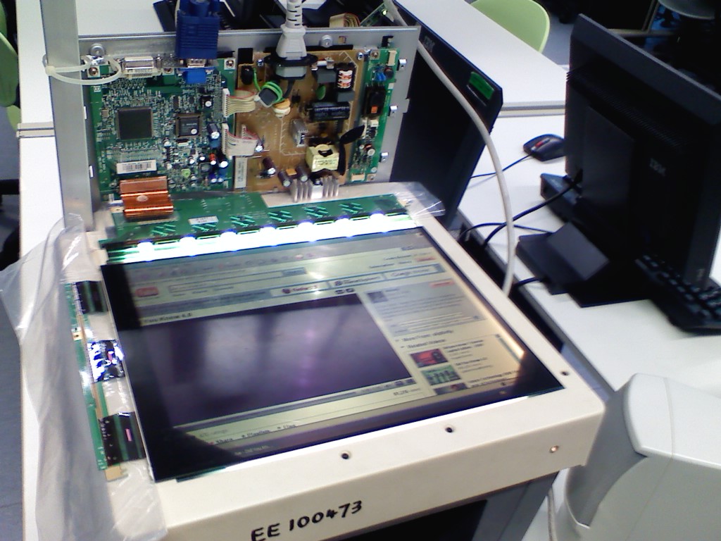
By reading up on how LCD monitors are constructed. I could have remove item2 on the picture and replaced the back light with a light source from the OHP and "tahdah" my projector! There go my frenzy search for spoilt LCD and OHP. DO NOT THROW away your old warez, breath new life into them. Alternatively, you can donate it to me! hahaha. I would like to thank monir, pauline and chin hee for sourcing the written off items or faulty items such as the LCD, OHP and tools. Items are really old and chuck in a dark corner, until i salvage them. Proceed with care. Observe are safety requirements and bleed the voltage store in the LCD monitor before proceed by disconnecting from the mains and let it sit for some time, I do not have a professional bleeding circuit on hand nor i am making one. Too hazardous.... 

What I have used.
1. 1x Phillips Brilliant 105p 15" LCD monitor (FREE)
2. 1x OHP (FREE)
3. 2 wednesday afternoon (PRICELESS).
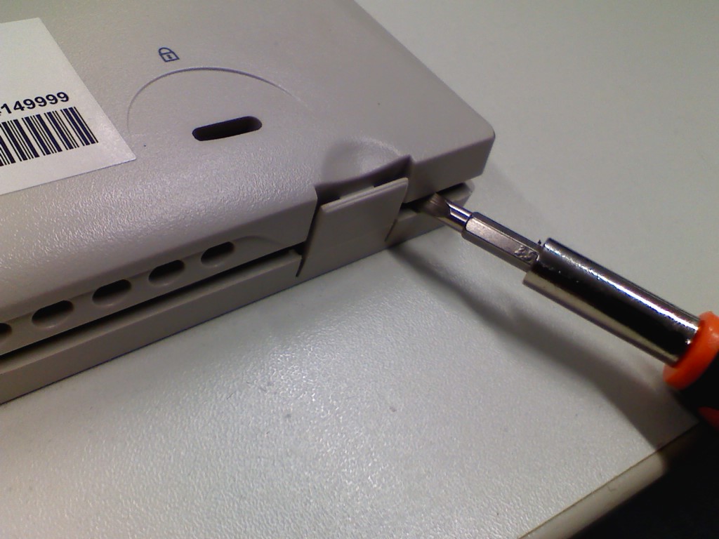


This is the LCD monir gets me. After removing the base stand from the LCD (requires some yanking and potential risk to crack the plastic housing), Unscrew the nut that holds the back panel to the LCD. Look out for the latch that hooks the lcd monitor housing in place. Usually, they come in a pair.
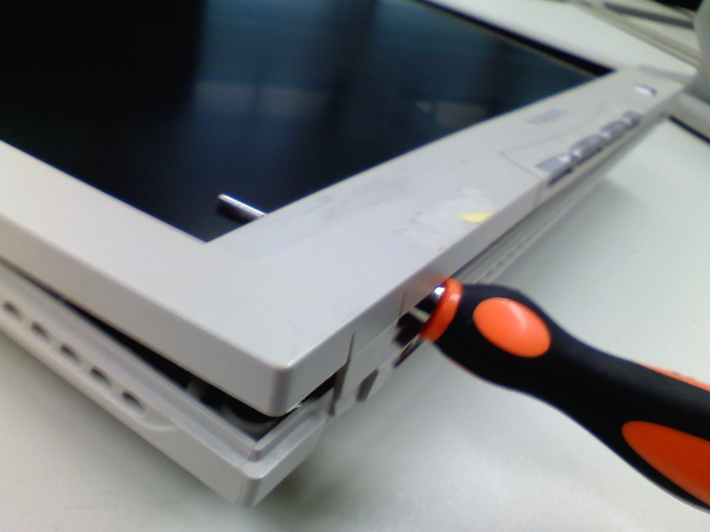


carefully lift the front panel cover after unlatching all the sides.
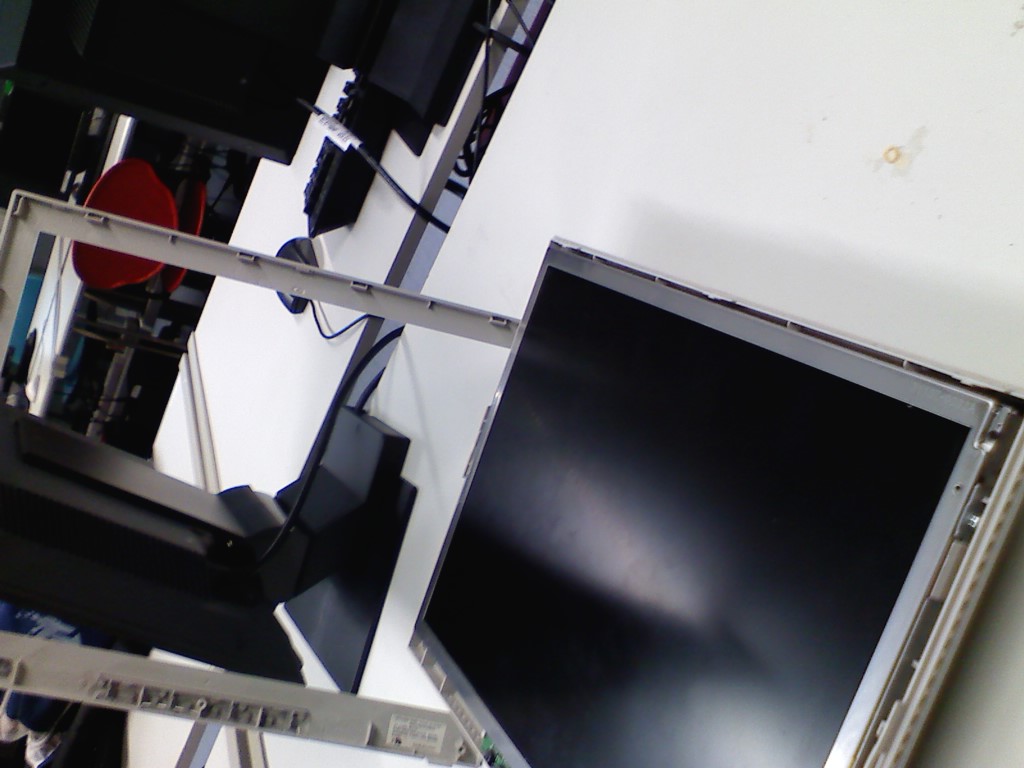


Remove the plastic front panel carefully, without damaging the hooks and latches.The black glass material in the picture above is the LCD. Handle with care.
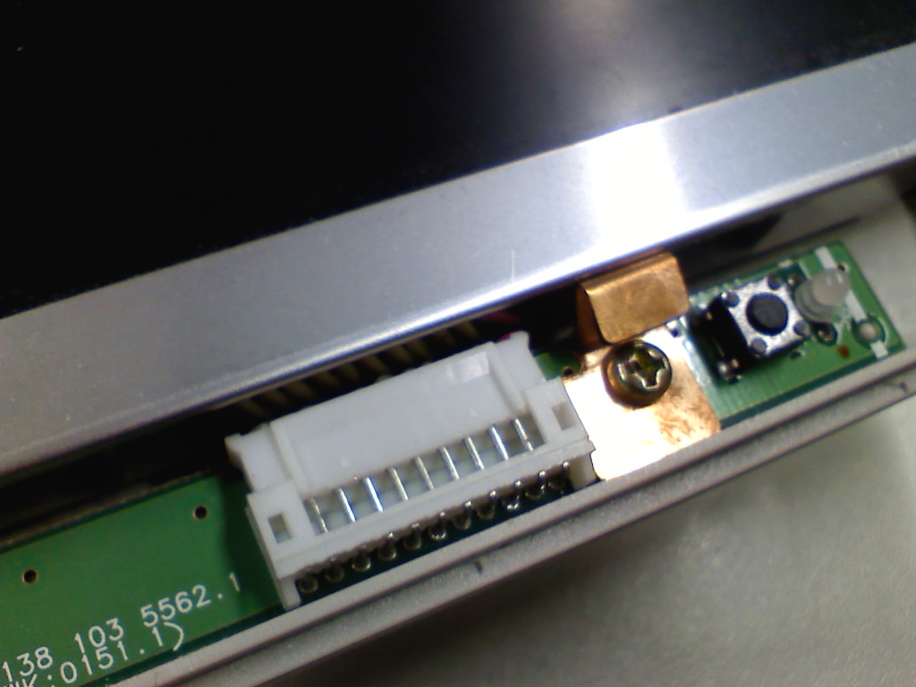


This is the connector for the IO panel which the power button resides. Remove with care. It will be used again in the later part.
The push button and LED to the right is the power button and power led.
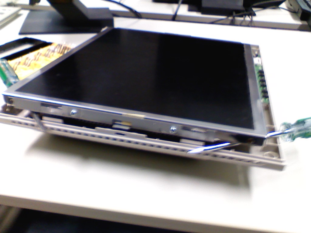

Carefully lift the black glass material that is hold in the metal frame. Here i used 2 screw driver as the lever to lift it up.
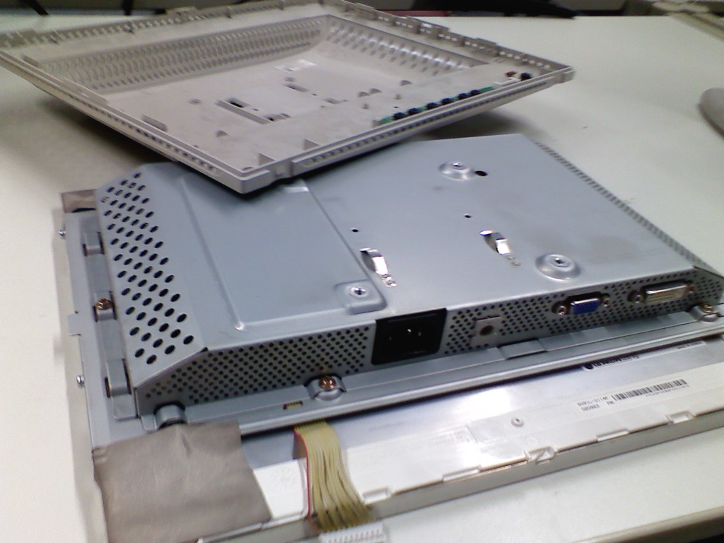


This is the reverse view of the panel lifted out. Inside the metal housing which sports the vga out, dvi out and the power socket is the controller board for the LCD. Basically power driver circuit for the back light and graphic display driver circuit for the LCD. The yellow ribbon cable is the ones we disconnected in the previous step.
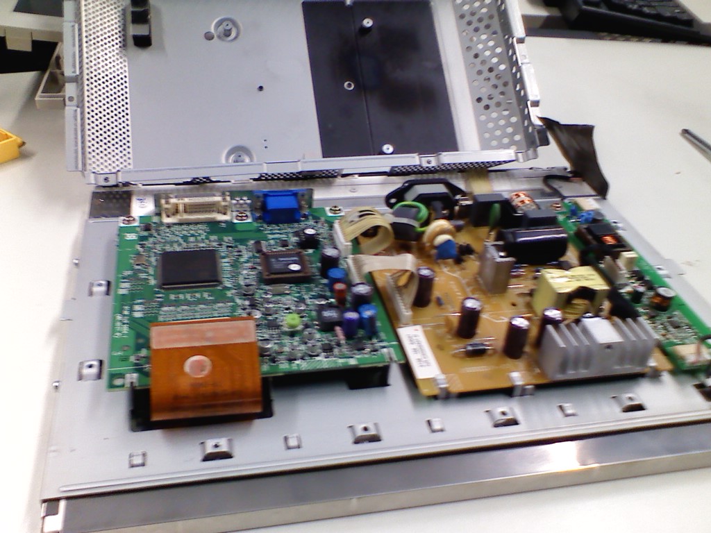


Unscrew the screw that holds the metal housing together. In this picture it circuits mentioned above. On the right is our power driver circuit to the back light. on the left is the graphics driver circuit. Note the orange coloured ribbon cable. Remove with care, because we are using it. I use my smallest flat head screw driver to slowly pry it off.


clearer picture. I removed the metal plate below, thinking of putting it in my plastic hobby kit box (for insulation). But the cables are simply too short to handle. To save time and hassle, i just use back the plate. More about insulation later.


This is how the ribbon cable looks like after it is disconnected. Gently peel of the metallic sheet, the black foam separator. They are self adhesive on the LCD.
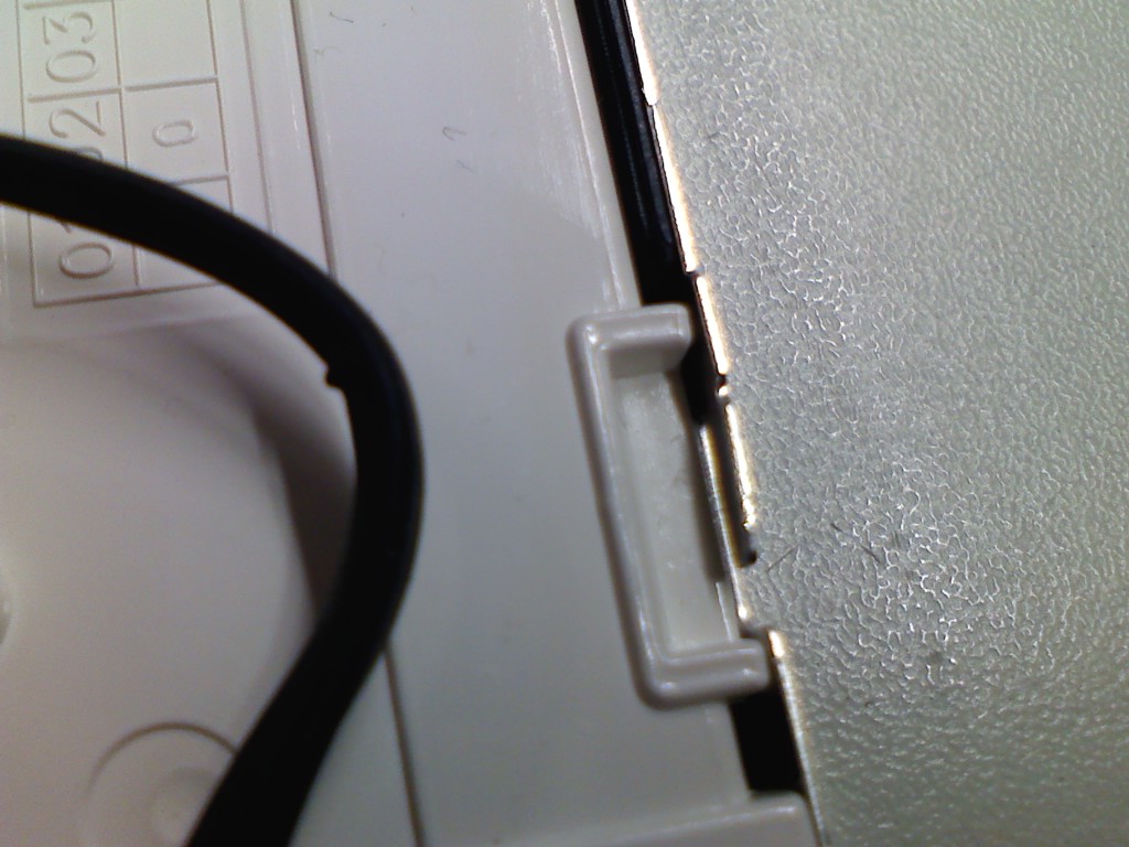


To remove the metal frame at the perimeter of the LCD from the panel is a little bit tricky. Because the metal pieces are bent towards the grove. So, just bent it the other direction as in the picture above.


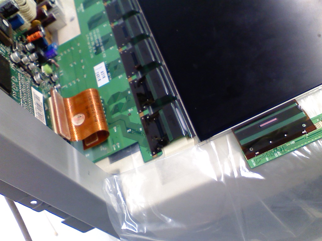
This is how it looks like after the metallic sheet is lifted out. The white colored plastic frame have to be removed from the LCD. The PCB is green in colour. Do not scratch, break or remove any connections from the PCB. These are the data lines to light up each pixel of the LCD.
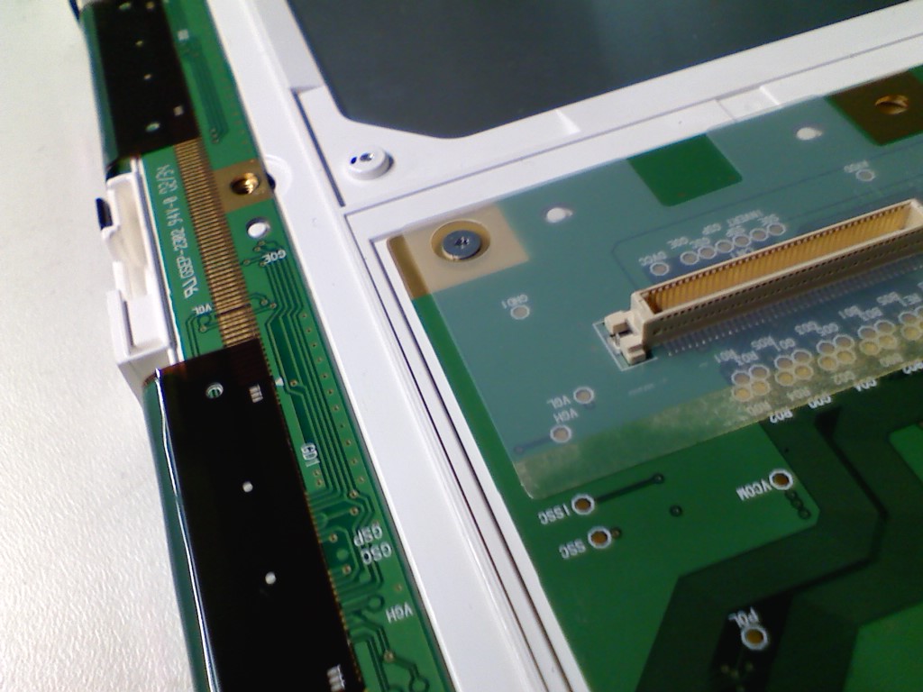


The screw in the above picture is the main hindrance for me to complete this project within the same wednesday afternoon. It is so small, such that all my screw driver bits will not fit. Luckily, pauline ,manage to source one from me. To the right is the connector to the LCD panel from the graphics driver circuit. To the left are the data lines connector. DO NOT REMOVE the plastic cover, those are the ribbon cable.


DO NOT remove the plastic cover that holds the ribbon cable. Unlatch the black latch to the white groove.
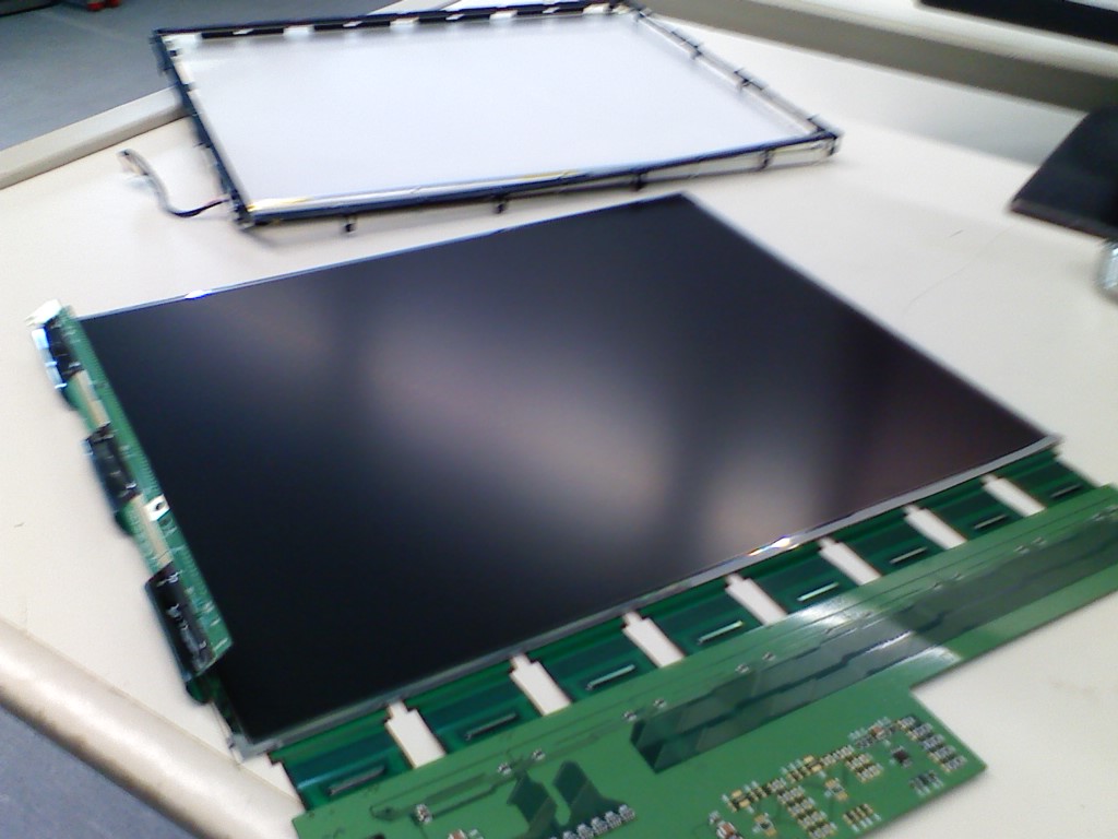


Behold, the LCD panel at all it's glory and the back light at the background.


we are using the lcd panel in black.
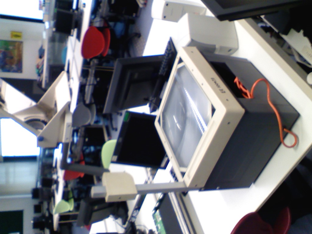


The OHP that chin hee get hold for me. It was dusty and littered with lizard poo. Got to clean it before use.

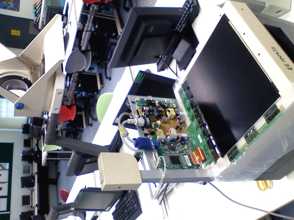
The next step is to snap the ribbon cable from LCD panel to the graphics driver circuit. Secure it somewhere to the OHP. I used 1 cable tie to secure it and laced some plastic sheet to provide some insulation. Assembly was a breeze. Please do not do it without supervision or safety precautions. 
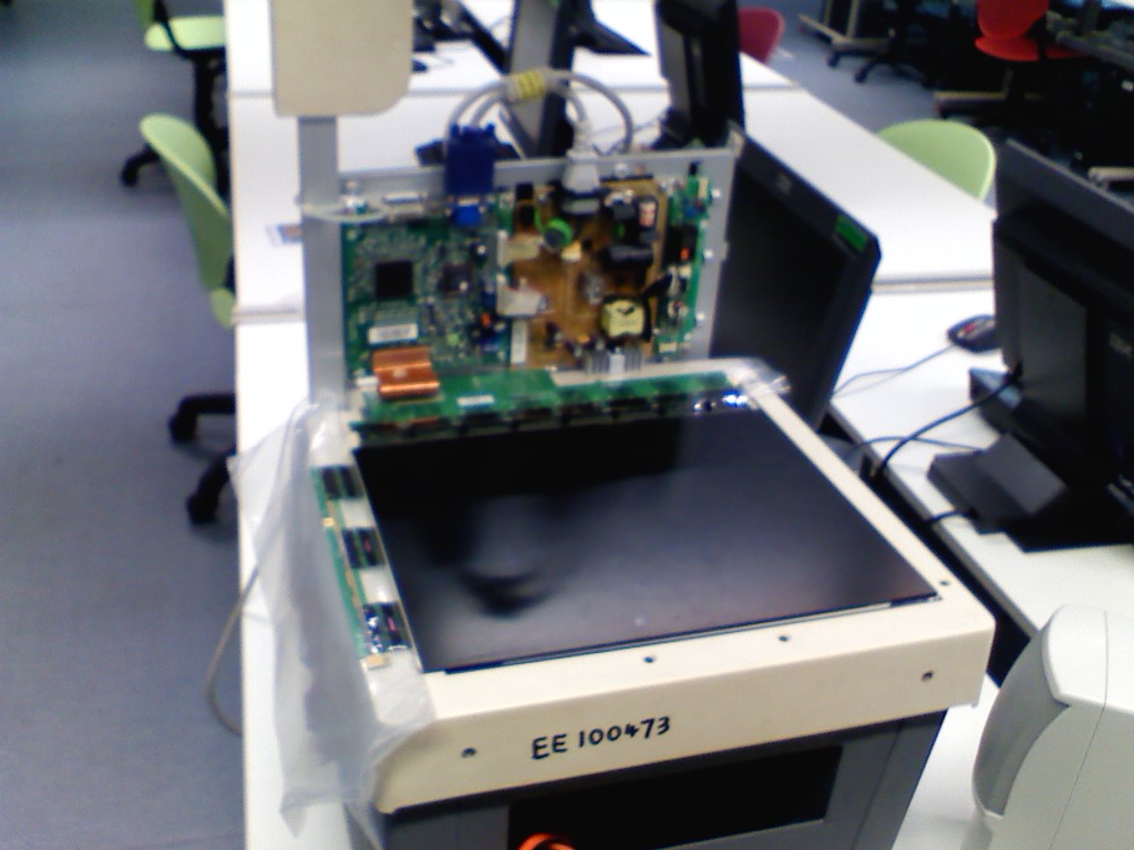


Now, the viola moment. Or i have another paper weight on my desk?
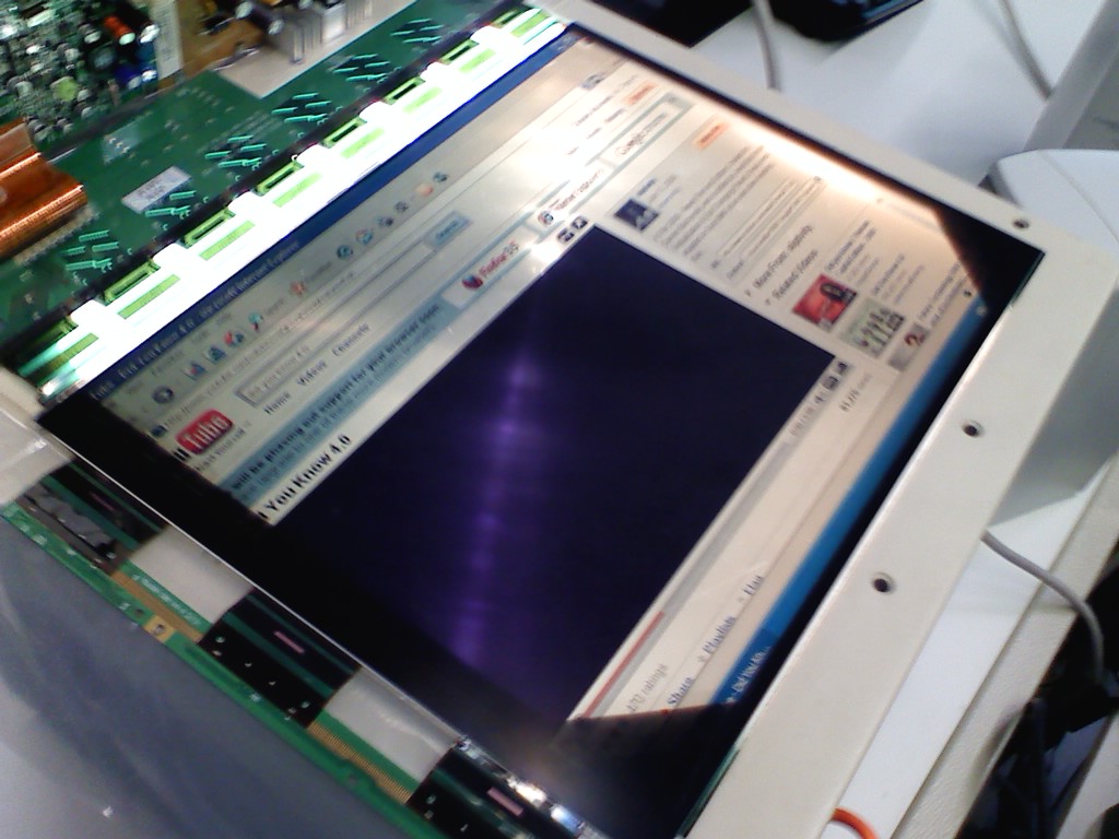

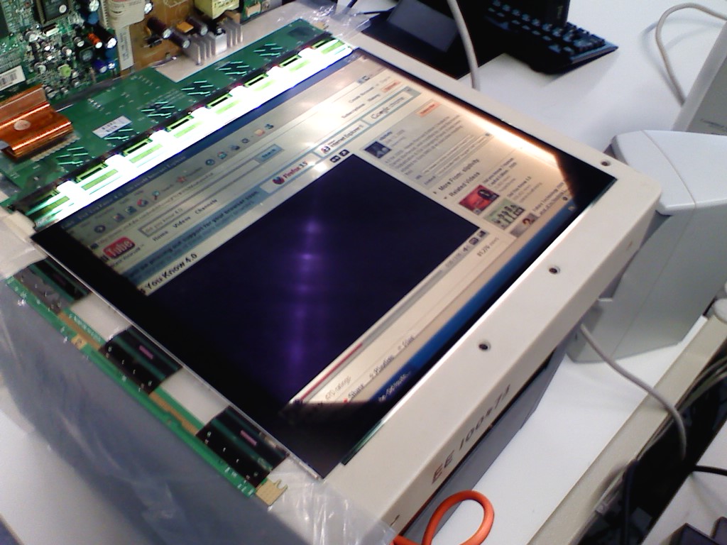
Look ma, there is picture in the well~
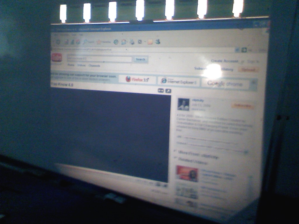

The projection is not as fantastic. It have a yellow tinge on display. I guess the OHP is really aged. Time to change to a xenon lamp!
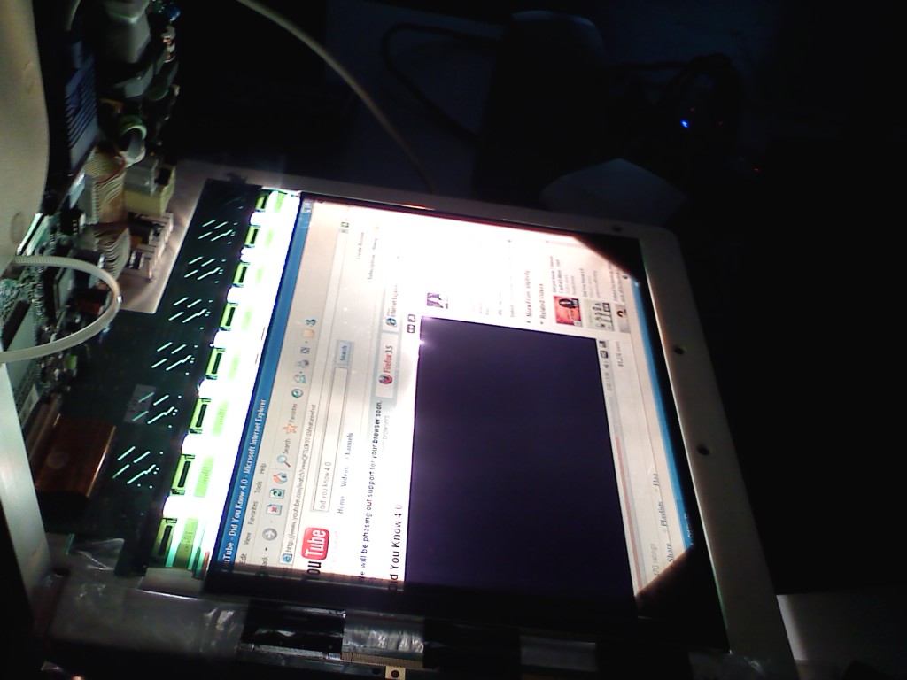


The end


Monday, November 9, 2009

[warez] USB plasma ball

After 3 weeks of agonizing wait, my usb plasma ball finally arrived~ yeaaayyyyyy!! 1 more coooool display in my office. I am another step closer to make my office into more disco-ish.

The best part of it, powered by USB, 5V and 110mA. Yet to try to power it with some dry cells. None to be found in my drawers. Arghhzzz

was discussing with yushan this morning, whether i can use his robo complete with the wheel to make a generator to power it. stay tuned


If you wonder what is plasma is all about, please read..


Wednesday, October 28, 2009

[DSA] posting of link in comment box

pls use HTML code

The following link is done with
www.google.com


<a href="http://URL" > the link < /a >


still figuring out how to post js in the comment box. as for entry, no problem encountered. If you have a solution to it, I did like to hear from you

Tuesday, October 20, 2009

[DSA] stun question Wk1


I came across this "game" when our department have a staff retreat at the Singapore flyer.
The objective of the game is to arrange staffs into 3 "E" characters.

Since this week our learning topics revolves around functions(), arithmetic evaluations, use of variables and proper programming methodology. I think it would be interesting to write a program to solve it. Anyway, during that period of time, access to a computer is a luxury. All equations have to be done on the paper. I manage to save this data in my memory and it is fresh still.

Attached is the screenshot of the piece of paper that illustrate the requirements.

Assume that the top and bottom horizontal bar is X, mid horizontal bar is (X-1) and the vertical bar is (X+1). Instinctively, this is a classic case where we can solve for X to the total number of staff and use it to form the "E". There is a possibility that there will be some staff remained, because we would want to maintain the uniformity of the 3 "E" characters.

3[(x-1)+2x+(x+1)] = total staff available.
which can further deduce to
12x = total staff available. => that is for forming 3 "E" characters.

Hence forming of 1 "E" character would be
4x = (1/3) staff available

The diagram below are not drawn to scale.

(x+1)
======== (x)
+
+
====== (x-1)
+
+
======== (x)

But how to translate the problem specs to code????????

we can use a divide and conquer approach to subdivide the problem into smaller portion.
Solving the algebra problem in the program might be redundant, since we have solve it on paper.

Some questions to ponder before start writing the code
a. what are the variables will be used.
b. do we need to use some form of data structure to store the temporary data?
c. what are the algorithms to calculate the X's, to display on the screen.

below are the sub-problem that need to be solve. drill down to further detail is not required.
1. Read in inputs from user for the number of staff available
2. Calculate how many will be left out from the E formation
3. calculate how many staff will form the top, mid and bottom horizontal bar
4. calculate how many staff will form the vertical bar
5. output to a screen

let the code and comments flow in!

Thursday, October 8, 2009

[DIY] Blinking LED bling belt buckle

Last Last week, attended one of my secondary school classmate's wedding. Btw, late Sept and early Oct I have already received 4x invites to wedding. More are in the pipeline..oh my goodnessssssss...........

Arghz, wedding reception is soOOooOoo boring. The food is usually not on par (mass produced), the alcohol is crazy (I'm in the brotherhood team, I'm used to blockade drinks targeting the groom.No drink driving please), lots of photo taking (I don't like to be the subject and I insisted to be photoshopped!!!! RAWRRR)

What totally grab my attention was my the first dish served, the cold platter. The lights are dimmed, Techno song was played (yeay!!!) and at the center of the dish there is this very "beng" blinking LED. It is in the shape of a dome, served in a cup of lightly coloured agar-agar (to give the light a medium to be illuminated). Quickly my I laid my paws on it before my bro daniel get to lay his! haha

Can' wait, I fished out my phone switch on the flash and tried to open the dome. But it is secured by screws! Well, I usually carry a handy tool set with me. No effort at trying to pry it open.

What drove me thinking was, how possible to pack 1 LED, some sort of controller/pic/MCU and battery cell small enough to fit into a dome shaped container at the size of a 20cents????

The content of the dome is just 1 LED and 2 button shaped battery (gives 3v). But, where is the controller???? Upon close inspection of the LED, i saw a tiny weeny black chip in the LED itself. That briefly explains the whole LED blinking sequences. My girl said I am "sua gu" (frog living in a well)...

well....I am pretty much exited with the "new" toy, open it up and find out that I can easily make 1 myself too without the hassle of wiring up a controller/MCU/pic and the considerations to make it small enough to be portable. The sample dome is in my office.

"Inspired" by this blinking LED, I was telling my trainees about this bling i going to make.
It is basically a belt buckle, complete with flashing LED.

Went Sim Lim Square (SLS) and Sim Lim Tower (SLT) last week for window shopping.

What?? Window shopping at SLS and SLT??? Not orchard ION, illuma? you gotta be kidding me!

Was hopping in and out of the shops in SLT looking for cool kit set and wares i can play with.
Chance upon this Flashing LED that cost 50cents each. They came complete default with flashing sequence, such that, there is no need to have a pic/MCU attached to the LEDs. Small is beautiful.

Initially, I only want to use 3v (button sized) to light up the LEDs, so all LEDs are wired in parallel circuit. Because there are too many branches and the current are divided at each branch of the circuit, it is not enough to drive the blinking LEDs. Normal LED are still OK. It Is in the circuit as a referencing point for the "beng-ness", lumens [brightness]. Actually, i only bought 10 of these. "LED not enough lar".

here I gave you my prototype belt buckle, 3v and 9v powered. Can spot the characters I am flashing?