For any open source products to be successful or adoption en masse by the "makers"/ "DIY-ers" / "dev" / "etc"; an up-to-date and accurate documentation or quick start guide has to be provided. User's posts in discussion forums are good, but the bits and bites of (usable) information are hidden in the troves, hiding deep inside irrelevant comments/posts. This might discourage the faint-hearted from "looking harder" at the problem. After scouring the Internet to find some leads on why the setup via "official" guide has failed, the good reads discovered are placed in the references section. From a seeming "easy" writeup on the SEEEDstudio official guide, it took many hours trying to troubleshoot the setup to make it to work..
To save you from the frustrating moments, let's cut the chase and go straight to what works. If you are interested on what doesn't work, read between the lines or skip the steps below till the "what works /does not work" section.
There are a few parameters that will make or break this setup. Due to unforeseen err in documentations/writeups, the following parameters that worked were result of bruteforced effort.
The parameters relevant to this setup are
To save you from the frustrating moments, let's cut the chase and go straight to what works. If you are interested on what doesn't work, read between the lines or skip the steps below till the "what works /does not work" section.
There are a few parameters that will make or break this setup. Due to unforeseen err in documentations/writeups, the following parameters that worked were result of bruteforced effort.
The parameters relevant to this setup are
ESP8266 version
Choice of "matching" baudrate (e.g 9600, 57600, 115200) for 2 set of serial comms: ESP8266<->Arduino, and Arduino<->USB serial monitor (hardware serial or software serial)
Choice of 5v and 3.3v bridging circuitry between Arduino and ESP8266
Choice of Arduino Mega or Uno, that affect the availability of serial comms
Choice of terminal software
Choice of code for testing
Yours truly recommends Arduino Mega with ESP8266, using either logic level shifter or voltage divider, and Serial Monitor.
Assuming you only have an ESP8266 and an Arduino, trying to make ends meet without another FTDI breakout board for the softserial, you are not out of luck. Check out the footer for the source code that uses RGB LED as indicator instead of softserial.
It is not fun to brute-force or conduct A/B tests to solve the equation of 6 unknowns to get a "hello-world" type of setup. Especially when the official manufacturer's guide has been written such a way to heighten expectations from the ground. Hello world tests on newly acquired hardware or software are meant to be quick to read/learn, easy to wire/setup, and straightforward for customized applications.
Hardware needed
Yours truly recommends Arduino Mega with ESP8266, using either logic level shifter or voltage divider, and Serial Monitor.
Assuming you only have an ESP8266 and an Arduino, trying to make ends meet without another FTDI breakout board for the softserial, you are not out of luck. Check out the footer for the source code that uses RGB LED as indicator instead of softserial.
It is not fun to brute-force or conduct A/B tests to solve the equation of 6 unknowns to get a "hello-world" type of setup. Especially when the official manufacturer's guide has been written such a way to heighten expectations from the ground. Hello world tests on newly acquired hardware or software are meant to be quick to read/learn, easy to wire/setup, and straightforward for customized applications.
Hardware needed
0. ESP8266 aka ESP-01. This one is manufactured by SEEEDstudio. It runs off 3.3v only; can be powered off arduino's 3.3v pin or a separate supply with 3.3v and 500mA. Do not plug a 5V source to it.

1. break out board for ESP8266. This is made of a 4x4 veroboard, PCB headers, and jumper header. Be sure to score a line to separate the copper strips from shorting the adjacent pins.

2. Serial comm options on Arduino(s)
ESP8266 and Arduino needs 2 serial comms; either 1 hardware 1 software or 2 hardware serial.
Arduino Mega is preferred because of the 4x hardware serial. The nett effect is serial0 can be used for monitoring on PC USB, serial1 or2 or 3 can be used for comms between arduino and ESP8266 to issue the AT commands
or
Arduino Uno and a separate FTDI serial to USB breakout board. In the references section, some writeups suggested the limited baudrate on softserial affects the readout of ESP8266 on serial monitor. (more about this later)
3. logic level shifter
Arduino speaks 5v and ESP8266 speaks 3.3v.
option A: plug directly the TX-RX pairs between arduino and ESP8266. If used, there is a risk of damaging both of them. You might get lucky for getting away with this? How many times you can get lucky?
option B: use a voltage divider circuit to divide 5v source from Arduino to 3.3v source for ESP8266. Acceptable methods, definitely much better that plugging in directly.
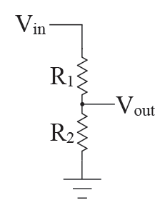
URL for voltage divider calculation: https://www.abelectronics.co.uk/tools/resistor-voltage-divider.aspx ; Vin is 5v, Vout is 3.3v, enter either R1 or R2 with a resistor value available at your disposal.
The following diagram decribes the setup with a 330ohm and 180 ohm resistor voltage divider circuit

option C: logic level shifter, e.g those sold by sparkfun. This method is highly recommended
option A: plug directly the TX-RX pairs between arduino and ESP8266. If used, there is a risk of damaging both of them. You might get lucky for getting away with this? How many times you can get lucky?
option B: use a voltage divider circuit to divide 5v source from Arduino to 3.3v source for ESP8266. Acceptable methods, definitely much better that plugging in directly.
URL for voltage divider calculation: https://www.abelectronics.co.uk/tools/resistor-voltage-divider.aspx ; Vin is 5v, Vout is 3.3v, enter either R1 or R2 with a resistor value available at your disposal.
The following diagram decribes the setup with a 330ohm and 180 ohm resistor voltage divider circuit
option C: logic level shifter, e.g those sold by sparkfun. This method is highly recommended

4. wiring scheme

Rule of thumb: always check pin out diagram before wiring, ensure common ground, vcc and gnd are connected according to voltage specs. ESP8266 CH_PD aka chip power down and RESET are connected to 3.3V for logic high; TX & RX pair for comms: ESP TX-> Arduino RX; ESP RX-> Arduino TXAssuming using Arduino Mega Serial2 (pin #16 and #17), ESP8266, and logic level shifter by sparksfun.
logical wiring schematic
MEGA ------sparkfun logic shifter -------ESP 8266
5V HV
3.3V LV
3.3V VCC, CH_PD,RESET
GND GND (both HV and LV) GND
TX(#16) HV chn0 RX---LV chn0 RX RX
RX (#17) HV chn0 TX---LV chn0 TX TX
3.3V LV
3.3V VCC, CH_PD,RESET
GND GND (both HV and LV) GND
TX(#16) HV chn0 RX---LV chn0 RX RX
RX (#17) HV chn0 TX---LV chn0 TX TX
the following diagram describes the wiring setup on a breadboard.

Software needed
Note: baudrate must match on both ends of a pair of comms device.
There are 2 serial comms as mentioned earlier.
0.0. baudrate for Serial comms between Arduino and ESP8266
0.0. baudrate for Serial comms between Arduino and ESP8266
Some sources on the Internet (e.g the official manufacturer's guide) recommended 57600, some forum posts recommended 115200. However the ESP8266 received (on dec14) was the latest version (0902) and the baudrate was set at 9600. Assuming all of the other parameters held correct, changing of this baudrate is not much of an issue. The following screenshot describes the ESP8266 software version in detail following a "correct" setup on both hardware and software. The main challenge is troubleshooting uncertainty on the hardware setup and software parameters.

0.1 baudrate for serial comms between Arduino and USB monitor
Assuming using hardware serial, any baudrate will do.
Software serial has a limited baudrate of 19200.
0. terminal software
0. terminal software
Hyperterminal, Arduino Serial Monitor, CoolTerm, SSCOM
Assuming using the hardware & wiring identified earlier, Arduino Serial Monitor can be used to monitor the serial output. The USB port on Arduino is by default Serial0.
1. what to expect
Powering up the arduino and ESP8266 setup.
Assuming using the hardware & wiring identified earlier, Arduino Serial Monitor can be used to monitor the serial output. The USB port on Arduino is by default Serial0.
1. what to expect
Powering up the arduino and ESP8266 setup.
The ESP8266 red led will light up, and flashes of blue LED during startup.
use a wifi capable device, look for ssid ESP_XYZABC; where XYZABC is the last 6 digit of the mac address of the ESP8266. By default ESP8266 start up in soft AP mode with DHCP, and any wifi capable device can be associated to this soft AP and receive IP address of 192.168.4.XYZ
Congratulations, ESP8266 is alive (if survived any of the misfortunes happened earlier).

2. source code for testing ESP8266 with Arduino
 The source code listed above merely copied data between 2 serial interfaces. Hence Serial Monitor can be used to enter AT commands via USB monitor on Serial0 to ESP8266 on Serial2.
make sure the parameters highligted in red in the screenshot are set.
from the serial monitor window, enter AT and then press "send"; assuming all parameters are set accordingly, an "OK" will be replied by ESP8266.
to reset the ESP8266, enter AT+RST and then press "send".
some random data will then appear, follow by "ready"
congratulations, ESP8266 is responding to some AT commands.
3. Source code for testing ESP9266 on an Arduino with Internet
An wireless router/AP is setup with the SSID "Edge", Security is set as "WEP", and DHCP. The WAN port of this AP is connected to the Internet. In the following diagram ESP8266 is connected to the AP, and issued with a private IP. However, the WAN port on the AP does not have an IP assigned, hence there is no Internet access.

The modified source code for testing is available on gist
Congratulations for coming thus far!! After all the hassle, Now, let's make some IoT inspired devices with ESP8266!!
Check out the URLs and PDF in the references section on what are the cool AT commands and configs for ESP8266
========================================================
Official manufacturer's documentation which doesn't work out of the box for yours truly
a few dependencies
1. the baudrate in the blog post is 57600 whereas the ESP82665 on hand is 9600, with no mentioned or whatsoever w.r.t it in the blogpost of the manufacturer.
2. the CH_PD & RESET are not held at logic high in the blogpost of the manufacturer.
3. open serial monitor and press reset on the arduino does not return any data at serial monitor. The main cause of frustration here is to figure out the no data displayed is caused by hardware e.g tx-rx pairs wiring, 3.3v and 5v circuitry wiring, etc or caused by software e.g baudrate on esp8266/usb or wrong code uploaded. The matter of fact, the statement itself is misleading. Assuming each and every parameter is config properly, there will be no data after performing the ritual of "open serial monitor and press the reset button on arduino" the magic lies at typing the command "AT" and then press "send" then the data will appear at output.
1. the baudrate in the blog post is 57600 whereas the ESP82665 on hand is 9600, with no mentioned or whatsoever w.r.t it in the blogpost of the manufacturer.
2. the CH_PD & RESET are not held at logic high in the blogpost of the manufacturer.
3. open serial monitor and press reset on the arduino does not return any data at serial monitor. The main cause of frustration here is to figure out the no data displayed is caused by hardware e.g tx-rx pairs wiring, 3.3v and 5v circuitry wiring, etc or caused by software e.g baudrate on esp8266/usb or wrong code uploaded. The matter of fact, the statement itself is misleading. Assuming each and every parameter is config properly, there will be no data after performing the ritual of "open serial monitor and press the reset button on arduino" the magic lies at typing the command "AT" and then press "send" then the data will appear at output.
Methodology & Observations: Setup(s) that does not work/ does work
MCU: uno
comm: serial0 only
code: "Examples->basic->BareMinimum"
en: 3.3v to ch_pd and REST
cct: voltage divider
baud s0: 9600
D0 rx-> tx ESP8266
D1 tx-> RX ESP8266
Serial mon on Serial0; AT and then "send" => no response
//-----------------------
MCU: uno
comm: serial0 only
code: "Examples->basic->BareMinimum"
en: 3.3v to ch_pd and REST
cct: voltage divider
baud s0: 9600
D0 rx-> tx ESP8266
D1 tx-> RX ESP8266
SSCom32 on Serial0; AT and then "send" => no response
//-----------------------
MCU: uno
comm: serial0 only
code: "serial0 setup with 9600"
en: 3.3v to ch_pd and REST
cct: voltage divider
baud s0: 9600
D0 rx-> tx ESP8266
D1 tx-> RX ESP8266
SSCom32 on Serial0; AT and then "send" => no response
//-----------------------
MCU: uno
comm: serial0 only
code: "serial0 setup with 9600"
en: 3.3v to ch_pd and REST
cct: voltage divider
baud s0: 9600
D0 rx-> tx ESP8266
D1 tx-> RX ESP8266
Serial mon on Serial0; AT and then "send" => no response
//-----------------------
MCU: uno
comm: serial0 only
code: "modified hello word with RGB indicator"
en: 3.3v to ch_pd and REST
cct: voltage divider
baud s0: 9600
D0 rx-> tx ESP8266
D1 tx-> RX ESP8266
Serial mon on Serial0 can't used
//-----------------------
MCU: mega
comm: serial0 only
code: "Examples->basic->BareMinimum"
en: 3.3v to ch_pd and REST
cct: voltage divider
baud s0: 9600
D0 rx-> tx ESP8266
D1 tx-> RX ESP8266
Serial mon on Serial0; AT and then "send" => no response
//--------------------------
MCU: mega
comm: serial0 & serial2 for ESP8266
code: "copy s0<->s2"
en: 3.3v to ch_pd and REST
cct: voltage divider
baud s0: 115200
baud s2: 9600
D0 rx-> tx ESP8266
D1 tx-> RX ESP8266
Serial mon on Serial0; AT and then "send" => OK; AT+RST and then "send" => ready;
=========================================================
ESP8266 on Arduino Uno with voltage divider circuit using serial0 and RGB led as indicator. Note the broken pin header on the arduino in the diagram.

References