Friday, April 30, 2010

Arduino with servo (360deg)

arduino with servo motor (360 deg) 


There are some servo code that came with arduino.
File->examples->servo->sweep


The servo is from parallax. It is a continuous rotation type. Courtesy of Ah Yap, TSO of T822.


I don't have a servo controller handy.... http://www.crustcrawler.com/downloads/manuals/ServoController.pdf
So I would just make do with manually programming my arduino to control 2 servo at a later stage.


The the servo takes 6v and 12mA and we do not want to power it directly off the MCU. If the current load is too high, 
the MCU might be fried. I really take good care of my arduino, so I will try 1x servo instead of 2x.


Just to illustrate the working of it.


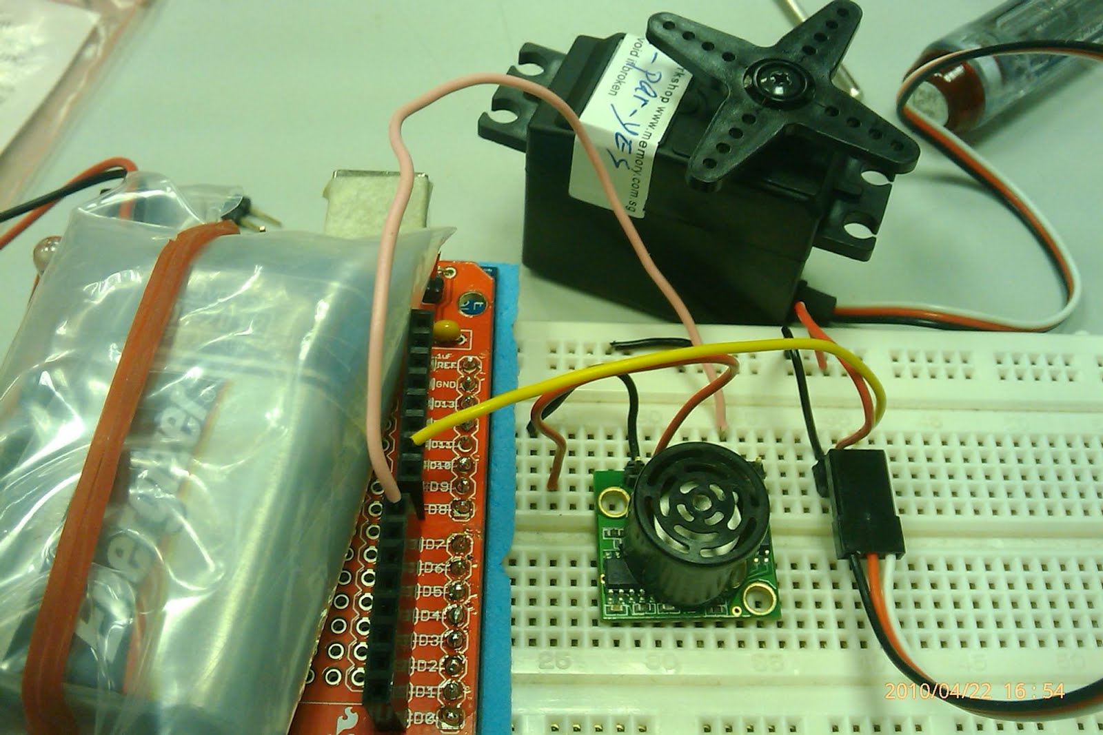
Ignore the sonar in the above picture. It is for decoration purposes.
Hook up servo +6v and gnd to arduino 5v and gnd, data to pin D10.


you can try try the example code "SWEEP" that comes with it and for convenience sake, it is attached below.


Check out the servo in action...

Now the questions come begging, how can we drive 2 servo using arduino (note: data pin only) for a forward and backward movement.

Arduino interface with maxbotic maxsonarEz1

Arduino interface with maxbotic maxsonarEz1

Maxsonar comes with a couple of flavours to interface, namely the analog and the pulse width. Below are the experiments I have done with them.


Connect MaxSonar pin 5v and Gnd to Arduino's 5V and gnd respectively. I am using Analog pin on max sonar, hence I connect it to A0 on arduino.


The ruler here is to help me to identify whether my readings are as accurate as possible. As I would put my hand across the sonar sensor at 15cm point and hopefully the readings will be 15cm too.

There are some sample code for sonar in arduino itself. I am using this from allen bruce. But he interface it to PING sonar instead.

http://snipt.net/teos0009/arduino-maxsonar-analog-pin/?key=2f06d19e68c5145fe0bbe650d3624ff8


The readings are plain crazy. 35x cm before I move my hand across the sensor. The analog pin is not accurate for short distance. But for longer distance where granularity in terms of 10s' of cm is still acceptable.

Next up, try with the PW pin. PW= pulse width. It is the Tc of the pulse generated by maxsonar that is measured. Wire to pin D8 instead of A0.


Same setup as previous. But the code have to change to reflect the method.

http://snipt.net/teos0009/arduino-maxsonar-pw-pin?key=327e03f8dfda55271e87ed42d99f16ac

 The data looks so much more interesting.......


Wednesday, April 28, 2010

Interfacing Arduino with wiimote (and later the nunchuck)


Interfacing Arduino with wiimote (and later the nunchuck)

I was toying with the idea of interfacing wiimote to my arduino as my replacement for accelerometer and gyroscope which comes in this package the

IMU Combo Board - 3 Degrees of Freedom - ADXL203/ADXRS614

 http://www.sparkfun.com/commerce/product_info.php?products_id=9249

which cost USD$124 which is equivalent to SGD$162.44. 
FYI, my wiimote cost me sgd$69 (left over from last year FYP project) and nunchuck sgd$25 (which I got from the shop at clementi city vibe where my student yenyu working part time).
Shall not elaborate about the wiimote and nunchuck...There are plenty of resources in the Internet.

I found out that the pin outs for the wii expansion port (WEP) from the Internet, thanks to the people that are willing to share the data! The drawing are for interfacing the IEEE1394 to the WEP.
Connect pin1 of WEP to Aref on arduino
pin2 of WEP to A5
pin5 to A4
pin6 to ground

I also found out that, it is not necessary to buy a nunchuck, cut out the connector part and used it with the wiimote. That, will render the nunchuck useless (to the Wii ofcourse, later you guys will find out more about my experiment with wiimote and why I have to use the nunchuck instead...........)
The replacement is a IEEE1394 male to male cable for sgd$7 from simlim square.

The pin out on the IEEE1394 and the WEP are carefully map out....

This is how it is going to look like, when they are connected...
Below are the code for sending and receiving data between arduino and pc. Similar code can be found at wiimeadows too! thanks to them for discovering the pattern of data send and receive out of the wiimote. 

below are the ASCII art for the data flow of the devices that are hooked up together.
arduino ---wired--->wiimote--bluetooth-->PC
arduino <---wired---wiimote<--bluetooth--PC

Some way, some how, when I open my hyperterminal to observe the data output, I only receive my debug message which is "serial init finished". This means my serial connection of 119200 is setup correctly, but no generated data is observed. No subsequent data is collected both from the arduino through the wiimote to the pc (need to use 3rd party wiimote driver, such as wiimote library on the windows OS), nor the pc through the wiimote to arduino (through hyper terminal). 

Used my multimeter to check the VCC and the gnd pin of IEEE1394 pin out, all seems to be correct. Just that no data is observed from the transferring between the devices.
Rewire the IEEE1394 again, with more meticulous effort put in... the result is still the same............................................

Fustrated, because if I can't get the accelerometer readings from the wiimote to arduino, my hypotheses of using it as my sensor would be false!!!!!!

I was contemplating to cut my nunchuck to retrieve the WEP PROPRIETARY connector..........because, I could still use the nunchuck on the wii (As if I got one, hahahah). If  In the end, I  decided to mutilate the nunchuck. Plug in the connector to the wiimote and the exposed end to the arduino.... No eureka moment.......... the data output is the same as the IEEE1394 cable........Very fustrated................................because of my hypotheses would failed..........................

But, which part went wrong?????? I am still finding the cause of it..........There are success stories on the Internet that used the similar setup.......


Before the last straw to be thrown, I tried to hooked up the nunchuck to the arduino instead. 
with the code attached below


Atlas.... some readings from the accelerometer on the hyperterminal...data from the nunchuck.......


Monday, April 19, 2010

[DIY]{arduino} POV

my POV (persistence of vision)

some years ago, i created a spinning LED display on my decommissioned hdd. I want to display message and time on the HDD while it spins. Basically I opened up the HDD, attached 7LEDs to it. Hook it up to a PIC16 which is the only MCU that is made available to me at that time. The result turns out to be very bulky, and I need to use a computer PSU (power supply unit) to on the HDD and a separate step down circuit for supply 5V to my pic16. During that time, I am still using a non-cam HP nor I have a camera and I do not document it down. BUT, the know how is already with me.

Ever since I got my hands on my arduino and my protoshield ready I have been toying with the idea of making 1 POV that is easy, less bulky and can fits in a palm in a snag. So that when I sing/dj in a concert, my fans would gyrate with their hands in the air and write a message for me with the POV (I hope is not asking me to stop singing!!). The EGO meter will shoot rocket high, so does my blood pressure. haha

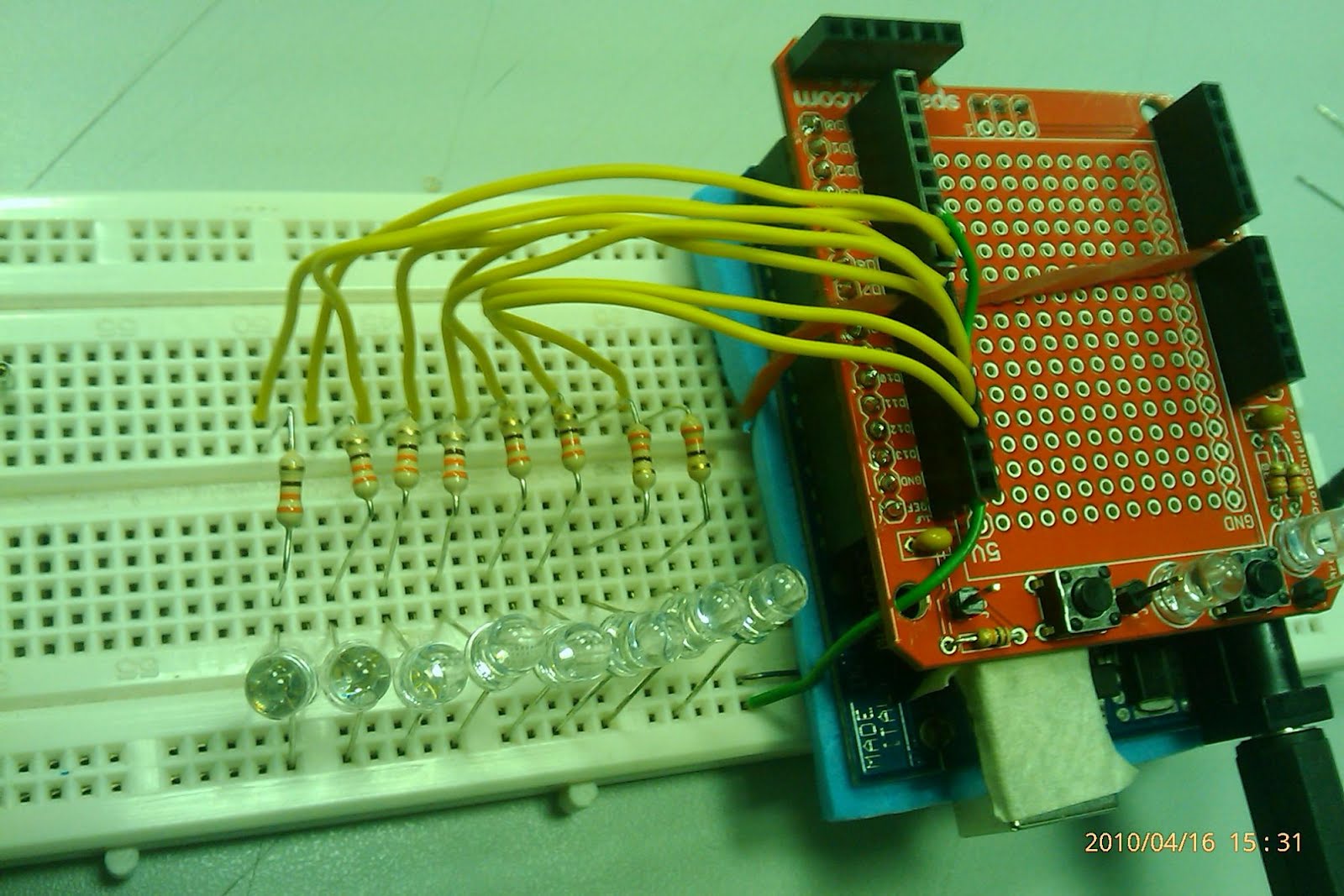
you would need 1x arduino+protoshield, 8x LEDs, 8x 330ohm resistor and code. 

I am using the digital output of arduino, current limited by the resistor to the LEDs. This is how it will look like after hooking up all the components.


The Idea behind POV is to play a trick with the human eye. It is a known fact that human eye see things at a rate of 27Hz.
That is our eye's refresh rate. So anything that refreshes above that rate, the eye cannot notice the flicker.


Say I want to display the character "E" in a 8x8 matrix, the col is indicated with col1, 2 and so forth.

col1, 2,3,4,5,6,7,8
********
*
*
*****
*
*
*
********

I would light up the matrix column by column and each of the column is differ by 2.5ms (400Hz), this is only to light up 1 character.
If I want to light up a message say "EEE", I need to repeat it the process above for each of the character.
Straight away, I know that I need some form of loop control structure to display column by column, and character by character.
Furthermore, I too need a data structure to hold the message. The easiest way is to store the characters in a 2D array.

To make my life easier, I am using this website to help me generate the 2D array for the message to print.

I have a code template for you to use.


After finish programming, I need to test that all LEDs are working at the init of the code. It is cumbersome to swing the breadboard together with the USB cable. Hence I made a 9V battery connected for it.
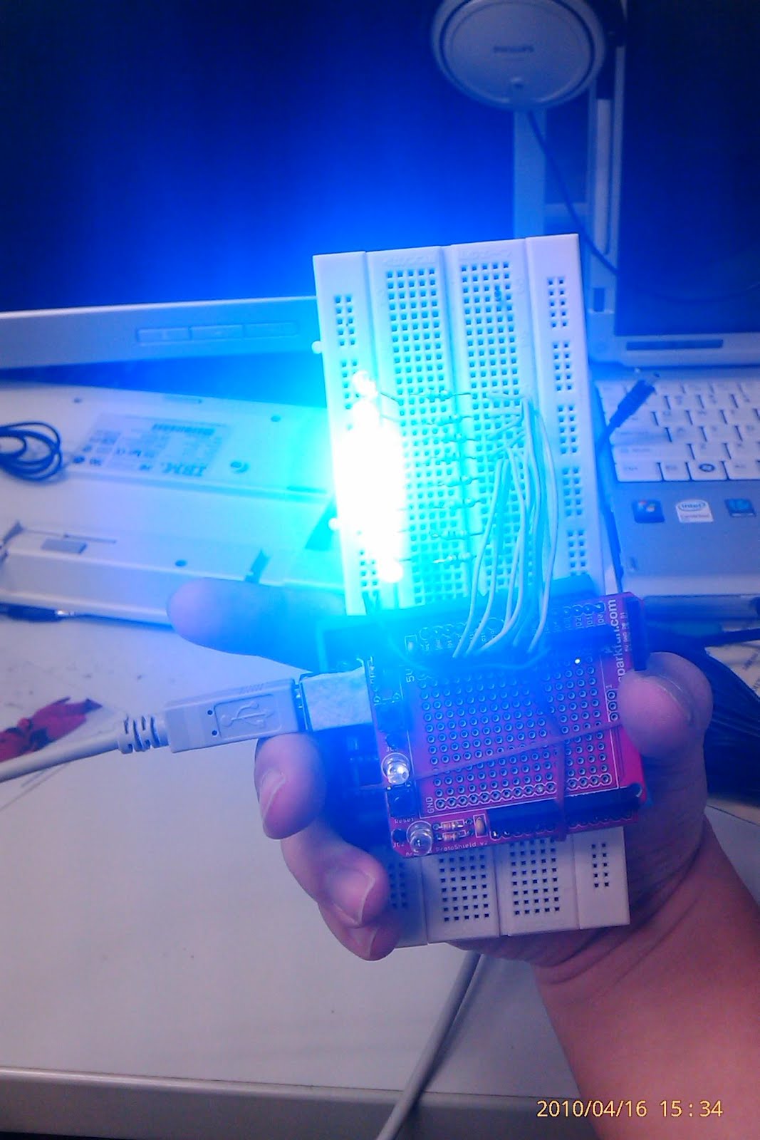
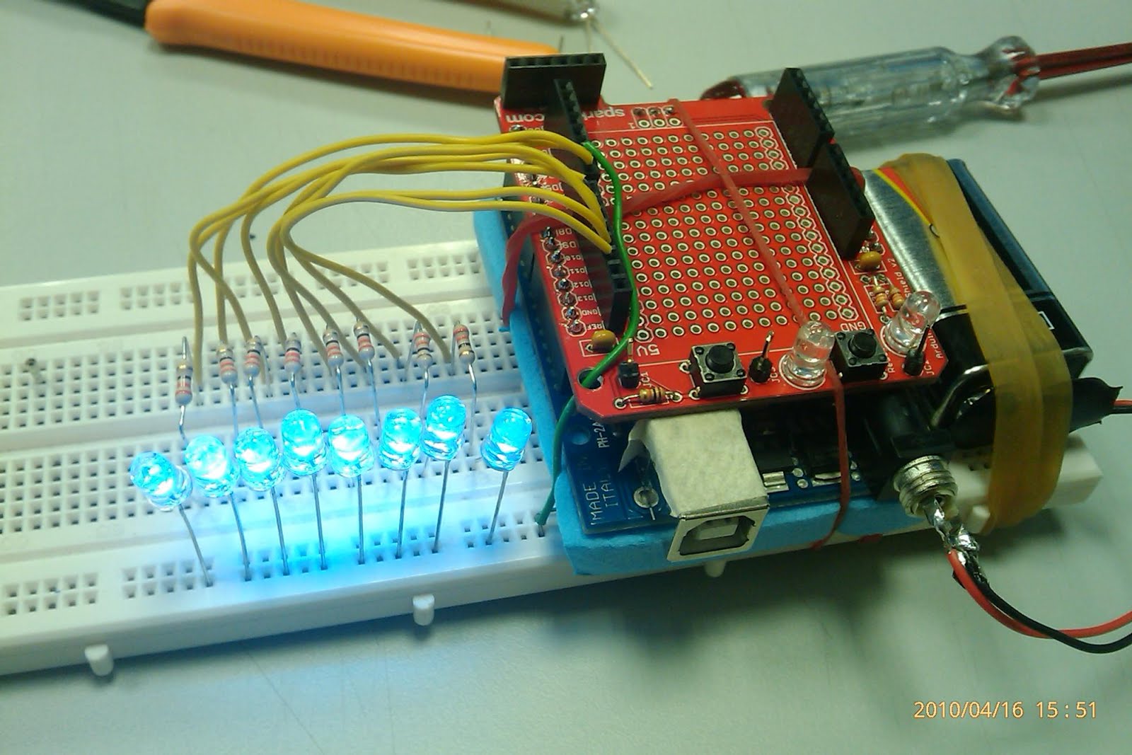

Below is an example of POV.... note that I hold my camera upside down....
What message am I printing????
What can place you can think of to use with this "toy" ??


[DIY] how to start programming with arduino


  1. Download image from the arduino website.
  2. Extract the downloaded file into a folderimage
  3. proceed to \drivers\FTDI USB Drivers and make sure the drivers are in it.
image
  1. Plug in arduino to the computer using the provided USB cable.
  2. When it prompts to install driver for the USB to serial converter, point it to the location where 3. is located.
  3. After installing complete, a reboot is necessary.
  4. Click on image to start programming.


<>
  1. This is how the IDE looks like.
  2. each project is called a sketchimage
  3. In this location, there are sample codes on how the arduino can be used. We will use file->examples->digital->button.image
  4. Make the connections for the LED and the switch. Connect JC1 to pin 2 and LED (JC2) to pin 13.
  5. Click on play buttonimage to start compiling. Once compiled, below screen will be shown. image
  6. Click on image to upload it to arduino.
  7. Press reset button on arduino after download to start the code uploaded.
  8. Happy programming.