[Arduino] Solid State Relay ( SSR )
Currently the DIY PRT prototype uses a HUMANGOUS 24V 10A mechanical relay + transistor circuit to switch between the 5V MCU digital pin and the 24V 10A DC supply to the motors.
In the next step of modularizing the building blocks of the DIY PRT into an Arduino Shield, that AWESOME relay could not fit into the shield. Worst part of it, the EM generated by the motors traversed the wirings and this affect the reading of the sensors. Previously, sparks was observed in the mechanical relay when the circuit turned on while the wheels were locked accidentally. If working in enclosed environment with dangerous gases (not fart pls), the spark might cause an explosion...Worst of it, there is no isolation of high current high voltage circuitry from the low voltage low current MCU. The circuit run a risk of frying the components at the low voltage low current side. Well, unless the opto-isolation circuit (opto-coupler) is included. The circuit get more and more complicated with each additional feature added!
The challenge here is to reduce the size of the relay, have opto-isolation and also simplify the circuit. SSR is here to the rescue~~~ http://en.wikipedia.org/wiki/Solid_state_relay
_________________________________________________________________________
One day while running some errands outside the office, I chance upon a SSR circuit from Mr.ChongSP’s D&I lab. It was displayed outside the lab.
Using my thick-skin-jutsu i approached the lab TSO and executed my BBS move on her. Mr.ChongSP and TSO Ms.Jana were more than happy to supply me a set of the SSR kit. thx! Look at the timestamp of the pictures, It took me more than a month to acquire, experiment and write down the experiment. Time is a rare commodity (exam, marking, checking, tallying, data entry, checking again)….If you have some spare CPU cycles, consider to supply me some.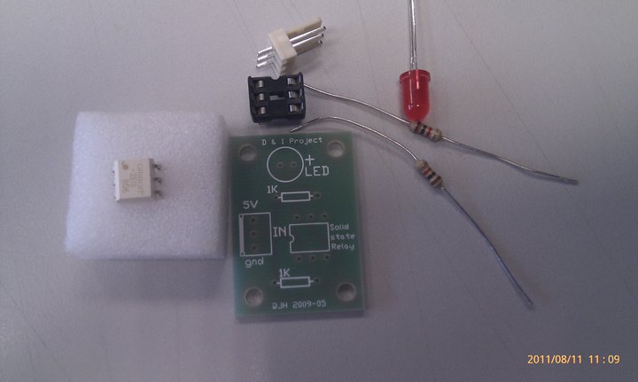
The TSO reminded me that this PCB connection is meant for DC-DC switching from low voltage to not so high voltage. But according to the specsheet of the omron SSR (I love omron relays!) http://www.omron.com/ecb/products/pdf/G3VM_351BE.pdf
This babe is capable of switching to 280V 100mA !!! Just to be safe, I only try to turn on a LED. lol. A quick peek at the specsheet, this babe is capable of switching DC-DC and also DC-AC depending on the configuration.
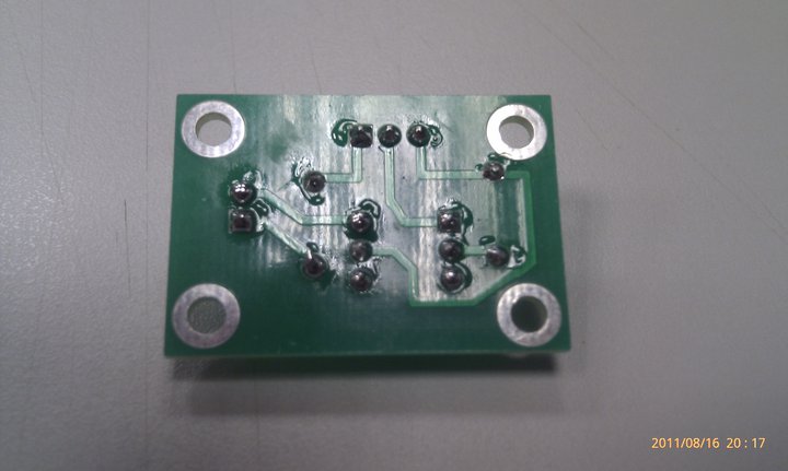
Soldering the PCB is pretty straight forward with the detail explanation on the silk screen. A point to note, when soldering ICs’ , never mount the IC to the IC holder while soldering the IC holder to the PCB. The heat form the solder might damaged the IC. An advise from my lab TSO many many years back when I was a student here. IMMA such a good student @@”

Only plug in the SSR when all the soldering is done.
Pretty neat huh...
Currently the DIY PRT prototype uses a HUMANGOUS 24V 10A mechanical relay + transistor circuit to switch between the 5V MCU digital pin and the 24V 10A DC supply to the motors.
In the next step of modularizing the building blocks of the DIY PRT into an Arduino Shield, that AWESOME relay could not fit into the shield. Worst part of it, the EM generated by the motors traversed the wirings and this affect the reading of the sensors. Previously, sparks was observed in the mechanical relay when the circuit turned on while the wheels were locked accidentally. If working in enclosed environment with dangerous gases (not fart pls), the spark might cause an explosion...Worst of it, there is no isolation of high current high voltage circuitry from the low voltage low current MCU. The circuit run a risk of frying the components at the low voltage low current side. Well, unless the opto-isolation circuit (opto-coupler) is included. The circuit get more and more complicated with each additional feature added!
The challenge here is to reduce the size of the relay, have opto-isolation and also simplify the circuit. SSR is here to the rescue~~~ http://en.wikipedia.org/wiki/Solid_state_relay
_________________________________________________________________________
One day while running some errands outside the office, I chance upon a SSR circuit from Mr.ChongSP’s D&I lab. It was displayed outside the lab.
Using my thick-skin-jutsu i approached the lab TSO and executed my BBS move on her. Mr.ChongSP and TSO Ms.Jana were more than happy to supply me a set of the SSR kit. thx! Look at the timestamp of the pictures, It took me more than a month to acquire, experiment and write down the experiment. Time is a rare commodity (exam, marking, checking, tallying, data entry, checking again)….If you have some spare CPU cycles, consider to supply me some.
The TSO reminded me that this PCB connection is meant for DC-DC switching from low voltage to not so high voltage. But according to the specsheet of the omron SSR (I love omron relays!) http://www.omron.com/ecb/products/pdf/G3VM_351BE.pdf
This babe is capable of switching to 280V 100mA !!! Just to be safe, I only try to turn on a LED. lol. A quick peek at the specsheet, this babe is capable of switching DC-DC and also DC-AC depending on the configuration.
Soldering the PCB is pretty straight forward with the detail explanation on the silk screen. A point to note, when soldering ICs’ , never mount the IC to the IC holder while soldering the IC holder to the PCB. The heat form the solder might damaged the IC. An advise from my lab TSO many many years back when I was a student here. IMMA such a good student @@”
Only plug in the SSR when all the soldering is done.
Pretty neat huh...
Now, connect the GND pin from the PCB to GND pin on Arduino (I found some students make this mistake when wiring up stuffs... The consequences may range from very small such as circuit not working to very serious such as sparks and fried MCU), VCC pin to 5V on Arduino and lastly signal pin to any one of the digital output pins on the arduino.

As for the code, I use the example code found at File->Example->Digital->Blink.
The SSR will be triggered at specific interval, turning on the LED. Phew.... everything work at 1st try. Now, time to wire this SSR to more interesting hardware (<10 V load plssss). Interested to play with it ????? dXD

No comments:
Post a Comment