Setting up the hardware for using Arduino as the In System Programmer (ISP) to download program onto ATtiny85
Parts Needed
1x Arduino Uno R3
1x Breadboard or 1x Veroboard
1x ATtiny85 (or ATtiny45)
1x 10uF 25V electrolytic capacitor
1x 220ohm watt resistor
1x LED
1x Breadboard or 1x Veroboard
1x ATtiny85 (or ATtiny45)
1x 10uF 25V electrolytic capacitor
1x 220ohm watt resistor
1x LED
- The following electronic circuit schematic describes the wiring of an Arduino to program an ATtinyXX chip. The LED and Resistor in the circuit are good to have, but not necessary. Warning: Orientation of the ATtiny85 chip DIP8 package relatively to Arduino is important during wiring.
- There are four possible choices of wiring up ATtiny85 chip to Arduino, each with its advantages and disadvantages. In this how to guide, the two most commonly used methods by enthusiast will be discussed.
- Breadboard
- Veroboard
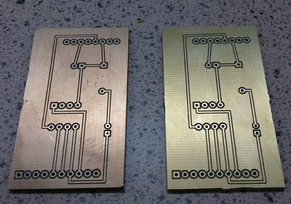
- Printed Circuit Board (PCB) custom milled
- Printed Circuit Board (PCB) commercialized
Setting up the hardware with BreadboardThis method is the easiest, effortless, least time consuming of the whole lot of methods. However, it comes with a few caveats. Question: What is the disadvantage of using a breadboard?
- Make sure Arduino is unplugged from USB when wiring.
- Refer to the schematic given above, wire up the Arduino and ATtiny85 accordingly.
- The following diagram describes the wiring on breadboard
- The ATTiny85 chip is now ready to be programmed. Refer to the how to guide “Setting up the software for using Arduino as the In System Programmer (ISP) to download program onto ATtinyXX” for the steps.
Setting up the hardware with Veroboard
This method is slightly challenging from the breadboard method. Skills require to make this veroboard is soldering, understanding of electronics principles, and also troubleshooting methodology. Question: What are the advantages as compared to the breadboard method mentioned above?
This method is slightly challenging from the breadboard method. Skills require to make this veroboard is soldering, understanding of electronics principles, and also troubleshooting methodology. Question: What are the advantages as compared to the breadboard method mentioned above?
- Prepare a piece of veroboard that is 20 columns wide horizontally.
- Align the components such as female header pins, 8pin DIP chip holder (for ATtiny85 chip), capacitor, LED, Resistor, and jumper wires with Arduino Uno R3 accordingly to the schematic given above.
- Solder the components to the veroboard.
- Refer to the following diagram for the reverse side of veroboard, i.e not the component side.
- The following diagram describes the veroboard ready for programming ATtinyXX chip.
- The “shield” (veroboard soldered with components to be used with Arduino) is now ready to be used to program an ATTinyXX chip.
Parting Notes:
Congratulations for making thus far!! You are now equipped with the necessary know how-to knowledge to quickly prototype an electronics circuit, and also making the circuit robust under unfriendly operating condition. The journey from schematics to breadboard and then to the veroboard is not the end; it is a starting point to an even more exiting journey of making your very own PCB. Allow me to put a teaser or two on the PCB making skills you are going to acquire in very soon into the future. See you at the other side of the rainbow.

References
ATMEL ATtiny85 data sheet http://www.atmel.com/images/atmel-2586-avr-8-bit-microcontroller-attiny25-attiny45-attiny85_datasheet.pdf
MIT Soft & Tiny Workshop http://web.media.mit.edu/~plusea/downloads/workshops/soft-and-tiny/soft-and-tiny-booklet.pdf
ATTiny XX for Arduino 00XX

1 comment:
great tutorial!!! i bought an arduino board from Arduino Uno R3 and i want to learn and use about it. please help me its basic use and tutorial sites about Arduino Uno R3
Post a Comment