Fujitsu E8410 laptop LCD panel LT154P3-L02 with LCD controller A.VST29.01
Couple of weeks back I gave my well-deserved Fujitsu E8410 laptop a break, with it broken down into parts level. The LCD controller A.VST29.01 I ordered arrived early last week. It is Chinese made, and I can even find a data sheet for it on the Internet. With proper documentations, gone are the days we have to make some educated guesswork on unknown PCB. The price is USD29.9 without the AC adapter (12V, 4A); USD 51 for the complete set.
My schedule is still as hectic as hell, at the office and during office hours I am distracted with human presence, spent most of the time solving other human’s problem. Only at the weekends in the dead silence of my office, I am highly productive. In this precious undisturbed time I get things done.
In the comment post some ask why I would take all the trouble to fix instead of buying new laptop. 99% time these are the trolls that are trying to promote their business on blogs that allow for comment. My answer: Re-purposing old electronics will reduce human’s dependency on Mother Nature’s generosity.
The boom in electronics driven by capitalistic consumerism has humans scrambling to mine lithium to be used in rechargeable batteries, fossil fuels, precious metals to be used in producing electronics circuit boards and more. It is just a matter of when natural resources will be depleted, and I am dead sure I will not survive to see discarded electronics in the landfill takes it natural cause to be turned into resources again. Prolonging the EOL of electronic products by repurposing into other usage should reduce electronic waste. Some might argue that using another piece of electronics to prolong EOL (End Of Life) is also capitalistic consumerism and driving consumption. True, but to a certain extend. I do not have the exact quantitative data to retort this rhetorical statement. Nonetheless, qualitatively, if 100 units of resources are used to manufacture a laptop and deliver it to end user, contrasting it with 10 units of resources are used to manufacture an electronic circuit and delivered to end user to prolong it; the projected 90 units of unconsumed resources would stay unmolested in the sacred earth reserves.
Major manufacturing house would love to silence disapproving voices like mine that might hurt their profit base line by not consuming/buying new stuff. The power is to the people with a choice, liberated with domain knowledge shared by inhabitants on the Internet. We are not alone.
Let the transmission of how-to begin.
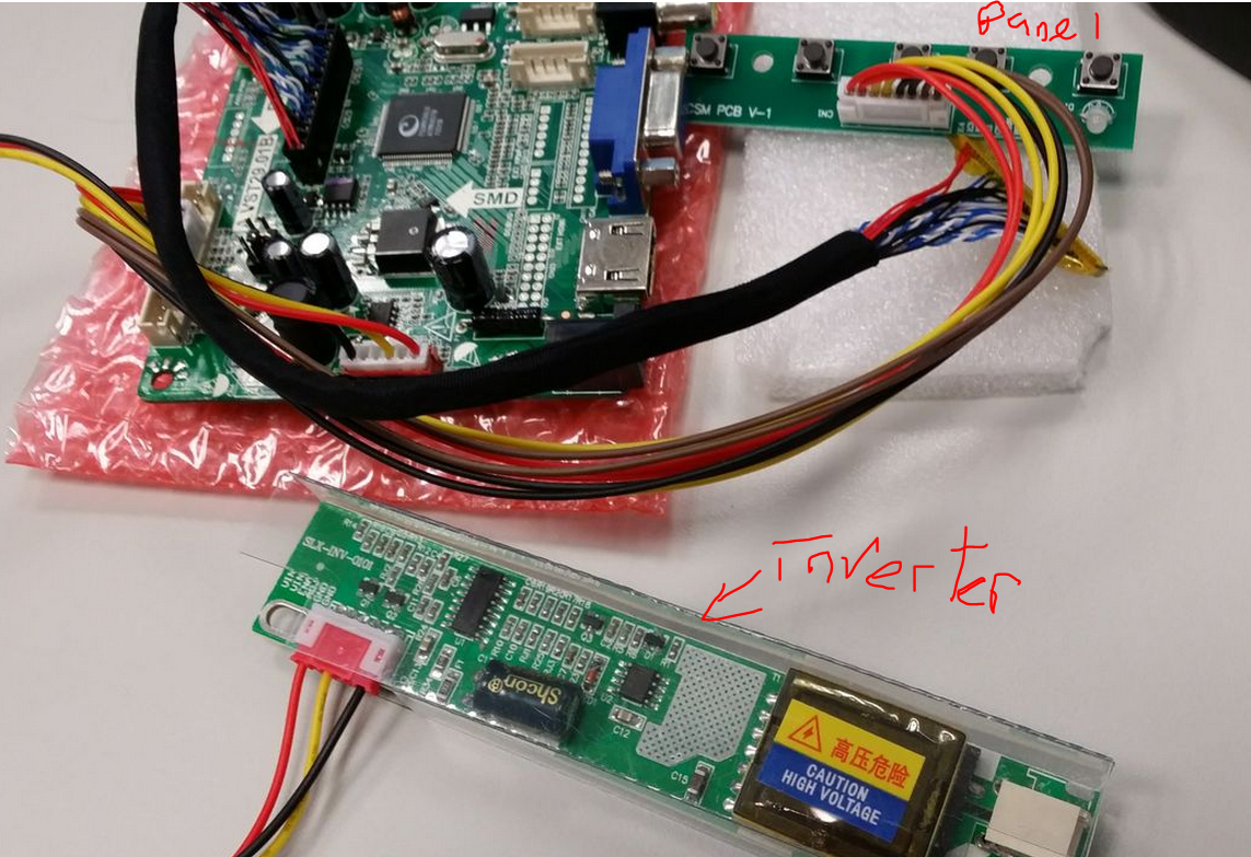
The package comes in 3 PCBs. The largest piece is the LCD controller, the larger rectangle shape PCB is the Inverter, it’s purpose is to power up the LCD panel’s backlight. Warning: the inverter contains high voltage during operation. Even it is disconnected from the supply, ensue safety precautions such as disconnecting from the mains, wear rubber sole shoes, not touching any bare metal area (soldering on the PCB are exposed to touch) are taken before handling the inverter PCB. There is a clear plastic surrounding the inverter. That is not meant for decoration, but prevents accidental in contact with the exposed area. DO NOT REMOVE THIS PLASTIC COVER! The smaller rectangle PCB is the panel where there are push button switches to control OSM (On Screen Menu).
The how-to is simple. Merely dismantle the LCD panel to the bare component level, remove the original LVDS cable and replace it with the one that comes with the LCD Controller. Some are weary of carelessness of flipping the connector and make a blunder out of it. No fret! The LVDS connector only goes in one direction, due to the design of it as depicted in the picture below from the LCD controller. Well, forcing the reversed connector definitely will damage the LCD panel and LVDS connector. The LVDS connector is replaceable, but not the receiving side on the LCD panel. 
The following diagrams depict the original cable in 3 states. “A” is written to depict the direction and also the orientation of the connector. Just my handy way of labelling things I am opening up for the first time and ensuring I can put it back as per the original state later.
After assembling the LVDS cable, this is how it is look like.
The bird-eyes view of the connection.
Circle in red is where the LCD panel’s back lamp is connected to the inverter. Square in red is the LCD controller’s LVDS cable connecting to the LCD panel. Some scotch tape is used to secure the wiring at a convenient location.
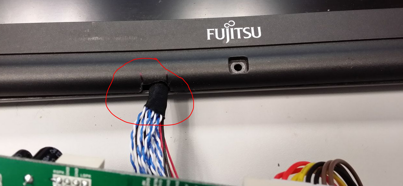
The E8410 laptop boasts a magnesium alloy casing on the LCD (that’s the reason I choose the model!!), and it is difficult to cut through metal with my bare minimal tools. So I have made an inconspicuous incision at the plastic area of the front cover to allow wiring to pass. 
A final check before turning it on! This step is very crucial! Do not skip the final check before turning on!!!
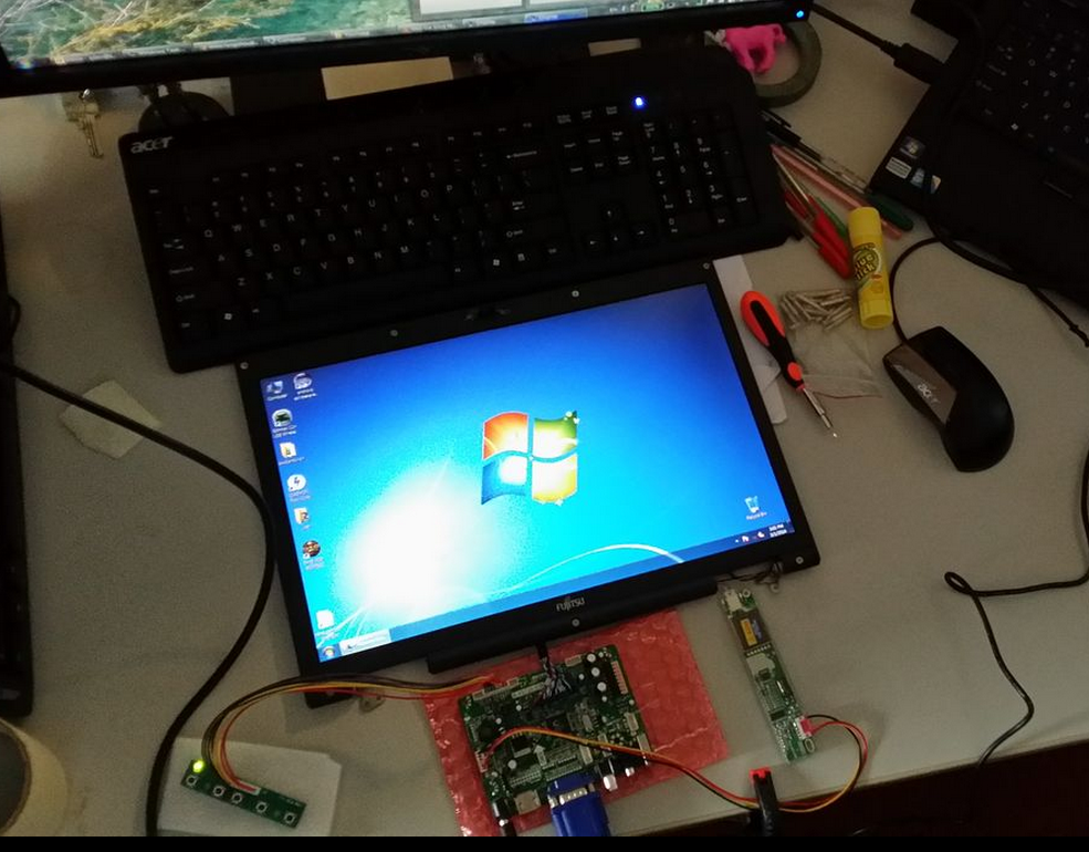
Turning it on, and familiarising with the OSM.
Connecting it to the vga of my gaming rig (i7, 8GB ram, 128GB SSD, GTX 550Ti, win7x64), it works at 1280x720. One short note, I connected it to the VGA of my office laptop (i7, 500GB,8GB ram, win7x32{I know, this is a piece of joke. Stop making fun of it}) prior to my gaming rig. I have tried a myriad of resolution from 640x480 to 1280x720. Unfortunately, office laptop decides not to co-operate. Luckily I have my gaming rig in my office to offer a second opinion. Otherwise, I would have to hastily conclude my weekend project in my office a failure. Oh, did I mention that my gaming rig is in my office???!! 
This weekend is the IT show in Singapore and I am such a cheapskate to spent very little $$. LOLx

2 comments:
Nicely done, Mr.Teo.
Post a Comment