Personally, I prefer to use LM35 as my temperature sensor instead of anything else. The reason is simple, it is bountifully available in our tech arsenal (just a mouse click and I can collect it from block T8), it is very simple to use with no extra circuitry, precision at +- 0.5degC within 0degC to 100degC, and literary it is plug and play with arduino. check out my previous post on getting started with LM35 and arduino. I am using this sensor for my arduino sousvide setup. After 6 months of abuse, it broke down, the waterproof temperature probe gave way, and water breached in it causing a short circuit. Shown below is my wiring for LM35; the optional 10K Resistor is there to suppress wiring capacitance that came with very long cables.
so my next course of resolution would be to get my hands on spare LM35, and also another method to water proof it. Little did I realise, a small little piece of LM35 is retailing at £1.99 per piece! To add salt to the wound, a pathetically sized 6cm x 4cm veroboard (stripboard) cost me £1.69 after 50% discount. The price gave me a real shock in my life. I always assumed that ICs are dirt cheap. The other possible explanation is that I have been living in the tech tower with a wide variety of ICs, PCBs, EE components at my disposable to make projects, losing touch with the reality. Arghhhh, how i miss my staffs at the procurement office. Not because of the complicated purchasing process I constantly bang into, but their effort to make sure we are well stocked.
After much googling around and also posting messages on my facebook to BBS (beg borrow steal). I came across websites such as TI are giving samples for free. Since I am staying across the pond and have an expensive looking email address, I can get my hands on 3 type of ICs with 3 samples of each in an order for free, and with shipping included too. As a backup plan, I also ordered a some ICs to complement my K type thermocouple that I have ordered earlier on amazon for £2.93 with free shipping.
The plan is simple. Solder a LM35, stick it into a brass radiator key I have idling around, and seal it with sugru. Sugru is going for £8 per packet of 5 mini sachets. I only needed one. My prior experience with sugru is a wasteful one. It has an expiry date that will be cured (harden) by than no matter what. Nonetheless, it is a good material to fix stuff. I posted a message on facebook group seeking partners to share the cost of materials; a kind soul from institute of making gave me 2 mini sachets for free!
Always test your equipment/stuff before sealing/cast in sugru or committing more materials on top of the equipment. In my case, i tested this waterproofed LM35 on my arduino before cooking an expensive piece of dry age beef. To my amusement, the temperature reading is fluctuating wildly. This is really bad signal to be the input for the PID control algorithm. It makes the tracking to the set point difficult and unreliable. To make the matter worst, the sealing of the edges on the brass radiator key with sugru did not went well as expected. When it is submerged in the water bath, I saw some air bubbles emerging from the thermo probe.
There can be a myriad of ways on what went wrong. leaky probe, faulty LM35, wiring capacitance that affects the reading, faulty pin on arduino etc etc. Thus, the great troubleshooting begins! I started off plug and play with another LM35 I soldered, but used a plastic bag instead for water proofing. Still the same old wildly fluctuating reading. After much troubleshooting and have exhausted all possible options, I tested the last piece of LM35 before solder and after solder. Ah-ha.... found the culprit. The solder iron is too hot for soldering ICs, and I have put it in contact with LM35 for too long a second.
Having busted 2 out of 3 of my LM35 and lost the 3rd in translation, I am back to my K type thermocouple. One reason that make me don't really like to use K type for my sousvide setup, is because it's temperature range is very wide, it is ranging from -260degC to 1400degC (manufacturer dependent). Divide the temperature range with 5v and than you will get what I mean. Reasons not listed exhaustively for my dislike include the requirement of a cold point compensation circuit for precision; signal output is in the range of milivolts per degC; it need an amplifier circuit to work, and can't connect directly to arduino; the amplification is not exactly linear for a cheapo amplifier which makes the code complicated to work with the circuitry; adafruit Thermocouple Amplifier MAX31855 breakout board going to cost me £16.80 from a UK dealer; and the list goes on.
Having said that, a very simple op-amp with a gain in the range of 100 would easily fit the bill for my setup with K type thermocouple. I just need to figure out the output voltage in milivolts of my k type thermocouple would output at the desired temperature for cooking, amplify it and normalized it to the temperature in degC. The first step is a re-visit to the data sheet of a LM358 IC, something I have not done for some time. To be frank, these ICs data sheets are not written for the layman in mind. Reading the data sheet not knowing what you need or a how to get things done will surely put off many people and abandon the project (not as if their livelihood depends on it). Scrutinizing the data sheet in detail, I just wonder why it does not include the classic text book example of a N-gain amplifier. I forsee that layman looking for something quick and fast through the data sheet will be disapointed and will spent hours trawling the internet for usable bits of info. How many will give up half way or abandon their project in due course of looking up for information?
The quick and dirty way of wiring of LM358 is at the self explanatory figure below, drawn by hand from yours truly.
B-side of the £1.69 veroboard. I still remember what was taught in my digital electronics class many years back. The hint is in the picture below.
Putting everything together for action. no smoke, no sparks. phewwww
I noticed the reading of the k type thermo couple from the LCD with comparison to my trusty digital thermometer. The final temperature read by K type thermocouple with LM358 is always biased at about 9 to 10 degC. This render the previous code useless. Nonetheless, it is easy to fix.
The only modification to the source code, from the code meant for
LM35-> temperature = (5.0*val*100/1024);
is modified to
LM358-> temperature = (val+9.5);
ARGHHHHH.... can you smell what the ROXXX is cooking?!
Monday, July 1, 2013
Friday, June 14, 2013
raspberry pi connecting to wifi in UCL using eduroam with parameters for IEEE802.1x
I have got my raspberry-pi setup for action with only a mouse, and I also configure the wifi for home use. As for school use, I have no qualms connecting to our CS network (cs.ucl.ac.uk); Somewhat to my dismay today, I am facing some frustrating moments when trying to configure my pi to connect to eduroam.
In my humble opinion, I think I am a good user because I would ALWAYS RTFM first even before any attempt to ask any questions. Most of my questions are answered not by person, but kung-foo manuals. The official wifi config guide for linux is listed here. As a good user, I follow the manual exactly to the word level and expect it to work. The reality is, it doesn't. It is mind boggling on why it will not work, especially it came from a reputable source. After an hour or so tinkering and troubleshooting, still no avail. Out of amusement, I decided to cat on the path to the file and the certificate doesn't show. Then I discovered that there was a typo in the path given in the OFFICIAL guide to the certificate necessary to facilitate a secure connection with eduroam. Prior to my cat, i only did a ls on the directory and saw the certificate, but the case sensitivity of the file name escapes saruman's stare.
Now come the second amusement of the day. On the guide it says use PEAP as authentication protocol. I did exactly that and it does not work. This is really weird because I am dead sure I got all my parameters correct. Again, out of amusement (actually more of out of desperation), I brute force possible combo of authentication protocol. I just picked TTLS at random and guess what?! IT IS ALIVE!!!
Now, the wifi config on raspberry pi to connect to eduroam in it's full glory is in the screenshot below. Use either the GUI method or the cmd method. The config flavours described in the screenshot is just for coparison/reference.
Cheat's 3 steps guide to 3D printing with makerbot replicator 2
I would like to thank the inhabitants of UCL institute of making http://www.instituteofmaking.org.uk/
the uploaders on thingiverse http://www.thingiverse.com/
My act is only possible with the altruistic vision that you uphold dearly.
step by step guide to 3D printing with makerbot replicator 2
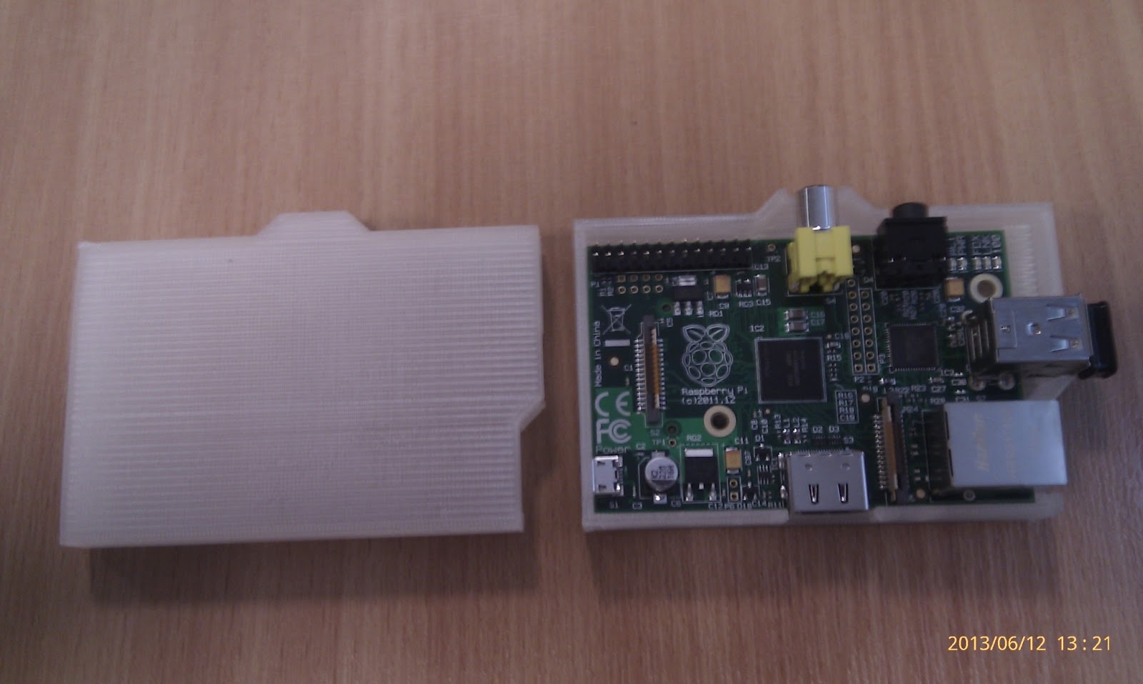
1. Download a "thing" from thingiverse, for example a raspberry pi case by redpeppr. http://www.thingiverse.com/thing:30572
2. Extract the *.STL from the zip file
3. use makerware http://www.makerbot.com/makerware/ to open the *.STL, align it on on the platform properly. click on the "make" button to generate the *.x3g file.
Select parameters such as % infill, thickness, number of shells, etc.
The slicing of the models will take some time, so if it stuck at 33% for "some" time, just let it continue to execute.
4. Copy the *.x3g file to a SD card and plug into the makerbot. Follow the instructions on the LCD screen on makerbot to start printing!!!
Optional step: Use online cad tools such as https://tinkercad.com/ to modify the *.STL downloaded from thingiverse as needed.
Sometimes, i want to save time by selecting 15% infill, but this caused the 3D printed model to collapsed while printing.
The final product: 3 shells, 100% fill; job time 2H56M
A poor lad's guide to install raspberry pi with no keyboard and no monitor
Gone are the days where I have the luxury of time, space and also the infrastructure. Long before I set foot in London, I was surrounded by 2x 23" HIPS LCD screens, 2 laptops, a few Us' of servers, and a few desktop tower of CPUs', all in my office, and not forgetting the departmental level techno arsenal that comes with each and every possible combination of connectors, cables, peripheral cards, and also the techno foundry lined with power tools, component racks, etc. Playing with my raspberry pi then is not much of an issue. I have the monitors, keyboards, mouses, wifi, cables, a cushy job that pays, comfy office, swimming pool, gym, MacDonald's, KFC, Starbucks, etc, you named it.
For now, I am only as good as draped in loin cloth. The only possession I have is my laptop, and a mouse, and my newly acquired raspberry pi. I left my pi back then, knowing that I might not have the lux to enjoy the fun with it. So, it is going to be a paradigm shift for me on how to start to play with my new raspberry pi model b without a monitor and also without a keyboard (note:it is phrased such a way to be picked up by the search engine). Knowing that the raspberry pi comes with a SSH daemon started when it boots, this I can use to connect via PUTTY to do some configs from my laptop.
The objective is to configure my raspberry pi without a monitor, without a keyboard, such that my pi will auto login to the GUI, because I do not have a keyboard to type in user name password, and also to type startx on the console for the GUI; connect to available WiFi (again, keyboard is needed to enter wifi credentials), ready with a virtual keyboard (can't afford keyboard, ARGGHHH) at every opportunity I could get my paws on a monitor. I got the HDMI cables for a mere £1.99.
*using nano, Press Ctrl-X to exit, and then follow the on screen instruction to save the file*
Part1 getting ready to configure raspberry pi
1. Prep a straight cat5 cable to connect the laptop and also the pi
2. Configure laptop's ethernet to 192.168.0.1/24
3. plug in the SD card loaded with raspbian-wheezy to the laptop's SD card.
4. locate cmdline.txt in the root directory of the SD card. Make a backup copy of it.
5. append to cmdline.txt with "ip=192.168.0.2" without the quotes at the end of the line. save.
6. plug the SD card into pi and turn on. Fire up PUTTY to SSH into 192.168.0.2
You shall be greeted with this screen
Part2 Configure auto login, auto start GUI, auto connect WiFi (to any SSIDs' that are available to me )
First thing first, the order of configuring this 3 components can be done in any order. I prefer to start to configure for WiFi First. This section requires you to connect to pi via SSH.
1. the command to get to the wifi config file: sudo nano /etc/wpa_supplicant/wpa_supplicant.conf
2. append the network related parameters corresponding to the wireless network with the block of code "network {....}". as per the screen shot, my SSID is "Edge", I painted red over my password. Use your own parameters. Replicate the network block to as many SSID you want to include.
3. type in the command sudo nano /etc/network/interfaces follow by the code as per the screenshot.
4. Reboot the pi with sudo shutdown -r now
LO and BEHOLD, you will be greeted with this screen. (*fingers crossed*)
5. Just to ensure the pi is connected to the internet (I have my WiFi network configured prior to configuring the pi), perform a ping as per the screenshot below to verify the connectivity.

6. Here, I am configuring for the autologin using the command sudo nano /etc/inittab , follow by the additional code highlighted in the red box as per the screenshot below
7. Here, I am configuring for the auto start the GUI using the command sudo nano /etc/rc.local , follow by the additional code highlighted in the red box as per the screenshot below
Part3. Internet goodness
1. The very first thing to do with rasberry pi connected to the Internet, is to update the raspbian with this command sudo apt-get update
2. The next thing is to install the virtual keyboard with this command sudo apt-get install matchbox
3. if you have any other software to install, this is the time to do it.
part4. Enjoy
Now i am going commando with my newly configured raspberry pi. you can do the same too!
*note: the 42" LED Toshiba TV, PS3 and controllers, iron, and 5.1 surround speakers are not mine to begin with* I am just another poor and jobless lad, struggling to make ends meet as a starving student.
Can you spot the virtual keyboard used to login to the wifi wall garden (UK only)?
For now, I am only as good as draped in loin cloth. The only possession I have is my laptop, and a mouse, and my newly acquired raspberry pi. I left my pi back then, knowing that I might not have the lux to enjoy the fun with it. So, it is going to be a paradigm shift for me on how to start to play with my new raspberry pi model b without a monitor and also without a keyboard (note:it is phrased such a way to be picked up by the search engine). Knowing that the raspberry pi comes with a SSH daemon started when it boots, this I can use to connect via PUTTY to do some configs from my laptop.
The objective is to configure my raspberry pi without a monitor, without a keyboard, such that my pi will auto login to the GUI, because I do not have a keyboard to type in user name password, and also to type startx on the console for the GUI; connect to available WiFi (again, keyboard is needed to enter wifi credentials), ready with a virtual keyboard (can't afford keyboard, ARGGHHH) at every opportunity I could get my paws on a monitor. I got the HDMI cables for a mere £1.99.
*using nano, Press Ctrl-X to exit, and then follow the on screen instruction to save the file*
Part1 getting ready to configure raspberry pi
1. Prep a straight cat5 cable to connect the laptop and also the pi
2. Configure laptop's ethernet to 192.168.0.1/24
3. plug in the SD card loaded with raspbian-wheezy to the laptop's SD card.
4. locate cmdline.txt in the root directory of the SD card. Make a backup copy of it.
5. append to cmdline.txt with "ip=192.168.0.2" without the quotes at the end of the line. save.
6. plug the SD card into pi and turn on. Fire up PUTTY to SSH into 192.168.0.2
You shall be greeted with this screen
Part2 Configure auto login, auto start GUI, auto connect WiFi (to any SSIDs' that are available to me )
First thing first, the order of configuring this 3 components can be done in any order. I prefer to start to configure for WiFi First. This section requires you to connect to pi via SSH.
1. the command to get to the wifi config file: sudo nano /etc/wpa_supplicant/wpa_supplicant.conf
2. append the network related parameters corresponding to the wireless network with the block of code "network {....}". as per the screen shot, my SSID is "Edge", I painted red over my password. Use your own parameters. Replicate the network block to as many SSID you want to include.
3. type in the command sudo nano /etc/network/interfaces follow by the code as per the screenshot.
4. Reboot the pi with sudo shutdown -r now
LO and BEHOLD, you will be greeted with this screen. (*fingers crossed*)
5. Just to ensure the pi is connected to the internet (I have my WiFi network configured prior to configuring the pi), perform a ping as per the screenshot below to verify the connectivity.
6. Here, I am configuring for the autologin using the command sudo nano /etc/inittab , follow by the additional code highlighted in the red box as per the screenshot below
7. Here, I am configuring for the auto start the GUI using the command sudo nano /etc/rc.local , follow by the additional code highlighted in the red box as per the screenshot below
Part3. Internet goodness
1. The very first thing to do with rasberry pi connected to the Internet, is to update the raspbian with this command sudo apt-get update
2. The next thing is to install the virtual keyboard with this command sudo apt-get install matchbox
3. if you have any other software to install, this is the time to do it.
part4. Enjoy
Now i am going commando with my newly configured raspberry pi. you can do the same too!
*note: the 42" LED Toshiba TV, PS3 and controllers, iron, and 5.1 surround speakers are not mine to begin with* I am just another poor and jobless lad, struggling to make ends meet as a starving student.
Can you spot the virtual keyboard used to login to the wifi wall garden (UK only)?
Monday, June 3, 2013
google chrome extension message passing, change manifest version 2 from version 1
I am exploring on how to make a google chrome extension (GCX) to experiment with an idea, and learnt a great deal from various internet resources.
For starters, I have used this dev page https://developer.chrome.com/extensions/getstarted.html and it only took me 10mins to get a hang of what is google chrome extension is all about. The whole notion of GCX that deviates from the usual C++/java methodology on compiling, linking, debugging etc is really a new experience.
Each extension has the following files: (to place in a folder on the local drive during dev)
To get the bulk of the workings of GCX, I learn from the dev overview to have a system's level point of view https://developer.chrome.com/extensions/overview.html
Now, come the complicated part. My idea is for a user to interact with the page, without interacting with the page at all. sounds vague? Basically, the purpose is to automate a user's interaction with a page through the browser to a backend processing server. after spending a few hours of reading, I came to realise that I might need to do message passing and also content script.
I skim through many tutorials but the one listed below is very detailled and comprehensive. Thus, become my tutorial of choice to learn content script, background page and also message passing
http://vikku.info/programming/chrome-extension/get-selected-text-send-to-web-server-in-chrome-extension-communicate-between-content-script-and-background-page.htm
For this tutorial to work properly, i have installed XAMPP with some dummy php code to handle the $POST data
Somewhat, the code from the tutorial above does not worked as per expected. I followed the tutorial word for word and yielded not functioning result. In my observations, the CGX does show up with errors on chrome->tools->extensions, and "inspect popup" was grey out. To make the matter worst, the right click context menu supposed to show "send to server" but not displayed. There is no ways of troubleshooting or getting around with it. After a few days of reading from various sources, CGX dev pages included, I finally came across the reason why it does not work and made few fixes for it to work properly.
The main reason for it not to work is the change in version 2 manifest from version 1 for chrome browser version >=18 as detailed in this page http://developer.chrome.com/extensions/manifestVersion.html#manifest-v1-changes
There are dev page that describe the process of changing to manifest ver 2 http://developer.chrome.com/extensions/tut_migration_to_manifest_v2.html
Changing the manifest to v2 alone will not solve the problem. The reason was because inline scripts were made a violation with this error thrown Refused to execute inline script because it violates the following Content Security Policy directive: "script-src 'self' chrome-extension-resource:". To fix this, the script from background.html is moved to a *.js file.
manifest.json
background.html
bg.js
myscript.js and popup.html remain the same as the tutorial
i hope this update will eliminate the wild goose hunt that I have experienced from the above tutorial. Excellent tutorial nonetheless.
For starters, I have used this dev page https://developer.chrome.com/extensions/getstarted.html and it only took me 10mins to get a hang of what is google chrome extension is all about. The whole notion of GCX that deviates from the usual C++/java methodology on compiling, linking, debugging etc is really a new experience.
Each extension has the following files: (to place in a folder on the local drive during dev)
1. A manifest file (similar to the function of *.h files needed for a code that calls library to function properly)
2. One or more HTML files (the "page" the extension used to process data unless the extension is a theme)
Optional: One or more JavaScript files (to handle interaction between the user, web page and also the browser in the form of message passing)
Optional: Any other files your extension needs—for example, image files
To get the bulk of the workings of GCX, I learn from the dev overview to have a system's level point of view https://developer.chrome.com/extensions/overview.html
Now, come the complicated part. My idea is for a user to interact with the page, without interacting with the page at all. sounds vague? Basically, the purpose is to automate a user's interaction with a page through the browser to a backend processing server. after spending a few hours of reading, I came to realise that I might need to do message passing and also content script.
I skim through many tutorials but the one listed below is very detailled and comprehensive. Thus, become my tutorial of choice to learn content script, background page and also message passing
http://vikku.info/programming/chrome-extension/get-selected-text-send-to-web-server-in-chrome-extension-communicate-between-content-script-and-background-page.htm
For this tutorial to work properly, i have installed XAMPP with some dummy php code to handle the $POST data
Somewhat, the code from the tutorial above does not worked as per expected. I followed the tutorial word for word and yielded not functioning result. In my observations, the CGX does show up with errors on chrome->tools->extensions, and "inspect popup" was grey out. To make the matter worst, the right click context menu supposed to show "send to server" but not displayed. There is no ways of troubleshooting or getting around with it. After a few days of reading from various sources, CGX dev pages included, I finally came across the reason why it does not work and made few fixes for it to work properly.
The main reason for it not to work is the change in version 2 manifest from version 1 for chrome browser version >=18 as detailed in this page http://developer.chrome.com/extensions/manifestVersion.html#manifest-v1-changes
There are dev page that describe the process of changing to manifest ver 2 http://developer.chrome.com/extensions/tut_migration_to_manifest_v2.html
Changing the manifest to v2 alone will not solve the problem. The reason was because inline scripts were made a violation with this error thrown Refused to execute inline script because it violates the following Content Security Policy directive: "script-src 'self' chrome-extension-resource:". To fix this, the script from background.html is moved to a *.js file.
manifest.json
background.html
bg.js
myscript.js and popup.html remain the same as the tutorial
i hope this update will eliminate the wild goose hunt that I have experienced from the above tutorial. Excellent tutorial nonetheless.
Subscribe to:
Posts (Atom)