Monday, October 10, 2011

[Arduino] Bi-Directional DC Motor Control

[Arduino] Bi-Directional DC Motor Control
As time to come, we need to control motor or maybe even motors using our arduino. The 40mA limitations on the arduino Digital I/O pins made the load for the projects somewhat limited to LEDs and small little motors meant for solar (mainly because these motors are low in current requirements). What if I want to control big motors and really BIG A$$ motors?

For tamiya motors (3~6v, <1A), I would recommend something such as the ArduMotor  shield available from sparkfun at the cost of USD$25.50 (retired from sales) or the MShield from adafruit at the cost of USD$19.50. I do have the luxury of using the earlier, add a heatsink with some thermal paste and run at 2A max per channel continuously before one of the wheel got stuck and fried one side of the shield. For really BIG A$$ motors at the range of 24V 10A, I used Sabertooth2x25 available from Dimension Engineering at the cost of USD124.99.

The issues with buying items from the Internet and to ship from US, the turn around time is toolong (or short at the expenses of the consumer), and vendors locally do not carry it in-stock. For simple motor driver circuits, it is just a L298 chip (or couple with L297 for stepper motor control) with the accompanying circuit. The real hassle is to wire it up on stripboard and solder it. Which deter many from getting it done.

I chance upon Mr.ChongSP’s D&I lab previously. Apart for the SSR kit, I also asked for the Bi-Directional DC motor control kit, which was meant for the PIC18 MCU sets. Thanks Mr.ChongSP!
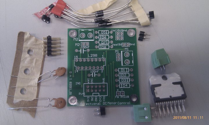
pretty neat huh.

After soldering up the components, it is time to wire up the tamiya DC motors to the motor controller to the arduino. Making the ribbon cable connector break out cable is such a chore and demanding on the eyesight. Luckily I got student junhan to help me on it.
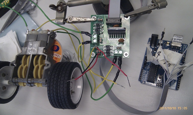
Attach the power source. +5v to the motor control (VSS) and >5v for the motors (VS).

Upload the code to Arduino and waiting for the magical moment...... after 2mins... still no sound, no noise and the motor control L298 is totally cool to touch. Something is very wrong here. Check connection, check code, check corresponding pin on motor control board to arduino and to code , just in case there is a mix up. No fault found. A quick check using the Digital Multimeter, only 0.2V measured across the DC motors. Seems to be dry cells I am using the current is not enough to drive the tamiya dc motors. Thus I swap to a 8.4v 200mAh GP rechargeable, only 1 side of the motor is driving. LOLx

A quick swap to conventional DC motors
Pheww... it worked


Time to source for some LiPO cells to play with my tamiya motors setup with the Bi-Dir Motor control board!

source code with comments here

Friday, October 7, 2011

[Arduino] Solid State Relay ( SSR )

[Arduino] Solid State Relay ( SSR )

Currently the DIY PRT prototype uses a HUMANGOUS 24V 10A mechanical relay + transistor circuit to switch between the 5V MCU digital pin and the 24V 10A DC supply to the motors.

In the next step of modularizing the building blocks of the DIY PRT into an Arduino Shield, that AWESOME relay could not fit into the shield. Worst part of it, the EM generated by the motors traversed the wirings and this affect the reading of the sensors. Previously, sparks was observed in the mechanical relay when the circuit turned on while the wheels were locked accidentally. If working in enclosed environment with dangerous gases (not fart pls), the spark might cause an explosion...Worst of it, there is no isolation of high current high voltage circuitry from the low voltage low current MCU. The circuit run a risk of frying the components at the low voltage low current side. Well, unless the opto-isolation circuit (opto-coupler) is included. The circuit get more and more complicated with each additional feature added!

The challenge here is to reduce the size of the relay, have opto-isolation and also simplify the circuit. SSR is here to the rescue~~~ http://en.wikipedia.org/wiki/Solid_state_relay
_________________________________________________________________________
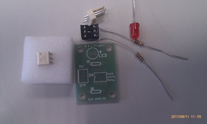
One day while running some errands outside the office, I chance upon a SSR circuit from Mr.ChongSP’s D&I lab. It was displayed outside the lab.

Using my thick-skin-jutsu i approached the lab TSO and executed my BBS move on her. Mr.ChongSP and TSO Ms.Jana were more than happy to supply me a set of the SSR kit. thx! Look at the timestamp of the pictures, It took me more than a month to acquire, experiment and write down the experiment. Time is a rare commodity (exam, marking, checking, tallying, data entry, checking again)….If you have some spare CPU cycles, consider to supply me some.
The TSO reminded me that this PCB connection is meant for DC-DC switching from low voltage to not so high voltage.  But according to the specsheet of the omron SSR (I love omron relays!) http://www.omron.com/ecb/products/pdf/G3VM_351BE.pdf
This babe is capable of switching to 280V 100mA !!! Just to be safe, I only try to turn on a LED. lol. A quick peek at the specsheet, this babe is capable of switching DC-DC and also DC-AC depending on the configuration.
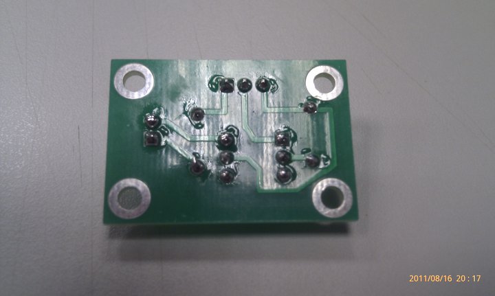
Soldering the PCB is pretty straight forward with the detail explanation on the silk screen. A point to note, when soldering ICs’ , never mount the IC to the IC holder while soldering the IC holder to the PCB. The heat form the solder might damaged the IC. An advise from my lab TSO many many years back when I was a student here. IMMA such a good student @@”
Only plug in the SSR when all the soldering is done.

Pretty neat huh...


Now, connect the GND pin from the PCB to GND pin on Arduino (I found some students make this mistake when wiring up stuffs... The consequences may range from very small such as circuit not working to very serious such as sparks and fried MCU), VCC pin to 5V on Arduino and lastly signal pin to any one of the digital output pins on the arduino.

As for the code, I use the example code found at File->Example->Digital->Blink.
The SSR will be triggered at specific interval, turning on the LED. Phew.... everything work at 1st try. Now, time to wire this SSR to more interesting hardware (<10 V load plssss). Interested to play with it ????? dXD

Tuesday, August 16, 2011

[Java] Credit Card validity checker using Luhn and known MII

I received an email from Mr.Chua yesterday seeking help on behalf of "dignitykitchen" to address the matter on
1. whether there is a way to differentiate the various credit/debit cards eg. AMEX, VISA, DINNERS etc?
2. Is it possible to read the card to get the card number and tell the type of card?

Suddenly the thought of using this as a case study for Java programming I assignment crossed my mind. 

Nonetheless, I could not wait till next semester to start to code and quickly hack up a POC using Java for Mr.Chua. Usually, I code in C++ or python, since we are going to learn Java Programming I soon therefore I shall code more often in Java. The implementation can be ported on C, C++, Java, python, android, arduino (to hook up with a magnetic card reader, more later) etc. As long as the programming "logic" is sound, it can be demonstrated using different language. It is analogous to saying "I love you" in different language..... You get the idea.

The code uses luhn algorithm to check the validity of the credit card number, through a series of steps on choosing alternate number starting from the LSB, perform calculation and finally a MOD10 . The code does NOT check the validity of the card with the credit provider. Features such as manual input, identifying credit card provider were added. The code base can be expanded to recognize more info from the number itself. 

Apparently I misinterpreted the word "read" from the email received, after realizing it from another colleague's suggestion on using magnetic card reader with an MCU to "read" in the data from the card and do the validation checks on the MCU iteself. Anyway, the validation code can be ported to the said MCU... e.g Arduino with a magnetic card reader.

NOTE: Source code is for academic use only.
1. place Main.Java and LuhnCheck.java in the same folder. Compile (I did it using javac) and run.

Main.java

Luhn.java

there goes my lunch time...... duhz.....

Sunday, July 24, 2011

loading external *.JS as per XSS

test external *.js, for the different flavours of XSS

">

Friday, July 8, 2011

[DIY] Arduino VU Spectrum Analyzer

While searching on the Internet on interesting way of approaching the purpose of doing Fourier transform and why we need FT for my teaching.

I came across a fellow arduino user (http://andydoro.com/vulol/) that posted his toy project on using Fast Fourier Transform (FFT) to make a VU meter. Couple of years back, I did played with my home made wireless VU using electronic components that is available from the store. I am quite surprised that  an 8bit Arduino is capable of doing FFT, never did I thought of using it because usually I am using a PIC32dsp for transforming from time domain to frequency domain for signal manipulation purposes. Arduino did gave me the WOW moment for a while.

From the detailed explanations on his website , i downloaded his code and hook up my LOLshield on my laptop playing some song to enjoy the geekness of arduino LOL shield VU meter.... To my dismay, it doesn't work "out of the box". It just display a 1 liner.... both plug in to my laptop and plug out from my laptop. Seems that the VU only picking up white noise from the ambiance. The connections are correct, pin A5 for +ve signal from the left channel and ground to common ground of the mini stereo jack. 


To further complicate the issues, I tried on a variety of input of devices ranging from my android phone, my speakers with a BIG ASS amp etc. Suddenly IT hit me, probably the analog signal read in at pin A5 is too low to be detected as a usable base band signal where the FFT would chop up the signal in time domain to be put into frequency domain and the harmonics combined as 14 outputs (LOL shield only have 14 columns of LED).

There are 2 ways to put the analog in on steroids. The hardware method, I would use a TIP31C or TIP41C audio amplifying circuit OR the software method by scaling up the data read in on A5. I choose the software method, it requires little time to prove my hypotheses compared to the hardware method.....

It is kind of worrying.... the VU is more sensitive now ,picking up ambiance noise which is reflected in the below picture. The LEDs are lighting up ....More work needed to change part of the code to filter AWGN....

But once I plug the mini stereo jack to a Y connector with the headphone stereo jack into my laptop, the noise signal disappear.
Played one of my favorite songs with rich sound texture... Sorry for poor sound quality... I am playing it through my headphone.... still office hour and I can't turn on the LOUD music...


enjoy the code. you would need to place the FFT and charlieplexing libraries in your arduino\lib\ folder to compile successfully.