Saturday, January 11, 2014

Design and fabricate a Printed Circuit Board (PCB) with Fritzing and cheat’s method to customize an Arduino shield

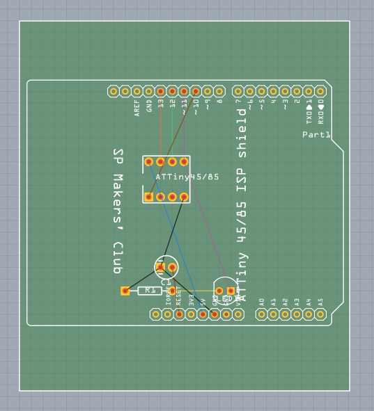
Design and fabricate a Printed Circuit Board (PCB) with Fritzing and cheat’s method to customize an Arduino shieldA sample screenshot of the Fritzing GUI, and a designed PCB ready to be fabricated.
Step 0: Download and install Fritzing, and familiarization with the GUI.
  1. Navigate to this URL http://fritzing.org/download/
  2. Download the Fritzing package according to your computing platform
  3. Extract the downloaded file into a folder of choice
  4. Install and launch by double clicking on the Fritzing Icon
  5. Familiarization with the Fritzing GUI. There are three tabs in the Main window panel, which offers electronics circuit in three different view. The “breadboard”, the “schematic”, and the “PCB”. Top RHS window panel offers pre-defined size of most commonly used electronics components, and also components from a myriad of vendors which include Arduino, Sparkfun, and more.
  6. The beauty of Fritzing. User can start by placing electronics components in the breadboard view or schematic view. Magically, the components will appear in the other 2 tabs that are not used. It is just a matter of preference where to start placing the electronic components.
  7. Once the electronics components are placed in the tab of choice, wiring to form the electrical connections between the electronic components can be made. The wiring connections will then be reflected in the corresponding two tabs.
  8. At the moment of writing, Fritzing does not offer simulation of circuits
Step1: Define an electronic schematic in Fritzing’s “schematics” tab
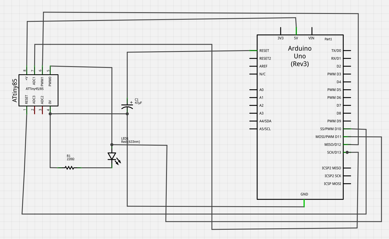
In this guide, The electronics schematic for ATtinyXX ISP shield will be assumed. While the methodology is generic, the electronics circuits should be user defined in the future use.
  1. Using the schematic above as a guide, call out the corresponding electronics components on Fritzing via the “Parts” window that is conveniently located at the top RHS panel into the “schematics” tab on Fritzing.
  2. Wiring for the connection of the components can be performed by click and hold on the point of one component, then release the click at the corresponding point of the other component. A wire will then appear.
  3. Check all wirings are done correctly and accordingly to the given schematic, in Fritzing.
  4. Now it is ready to proceed to PCB design by clicking on the PCB tab.
Step2. Design and Fabricate a PCB
In this guide, the ATtinyXX ISP shield will be assumed as an example to demonstrate the how-to of designing a PCB. A few points to note: PCB unit cost is related to two pricing components, the PCB footprint (the size of the board), and the number of layers (the copper threads layer). In other words, a smaller PCB foot print with single layer is cheaper than a bigger PCB foot print with double layer.
  1. Start PCB design by clicking on the “PCB” tab.
  2. The following screen shot best describes the designing process.
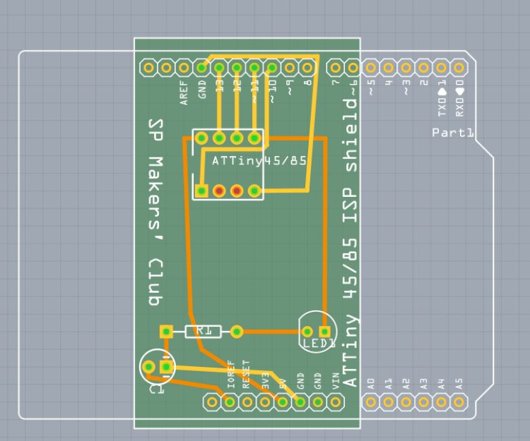
PCB resized and manual routes for double layer                       full size Arduino PCB foot print without routes
  1. In the screenshot above, the green box is the foot print of the PCB, the colour coded wiring corresponds to the wiring of electronic components made earlier. The human readable white colour text on the PCB is referred to as the “silk screen”, and it is customizable. The white colour shape outlines the physical perimeter of an Arduino and the relative position of the two rows of header pins. Using this predefined template from Fritzing, the to-be-created Arduino shield will fit the Arduino in a snug fit.
  2. Next is to add the routes. Routes on the PCB refer to the wiring of copper threads that connects electronic components. There are two camps or school of thoughts when it comes to placing routes on a PCB. First is the “auto-route” that requires minimal human intervention. Lastly the manual route that requires a lot of human attention. Placing of routes requires both functionality, and aesthetics. The routes must not be not too close to each other, and not overlapping to each other causing a short circuit.
  3. At any time when designing the routes in Fritzing, routes can be deleted or undo.
  4. Auto route by pressing the “Auto Route” button in Fritzing
  5. Manual route by clicking on the individual wires from one end to the other end.
  6. When route design is finalized, perform a design rule check by pressing Ctrl+Shift+D. Fritzing will recommend if the PCB design is ready to be fabricated.
  7. Export the PCB design into gerber files (RS-274X) by clicking on the “Export for PCB” button and send it to your local vendor to fabricate.
  8. The generated gerber files can be view using open source software such as gerbv.
Step3. Design a custom foot print PCB Arduino Shield using cheat’s method
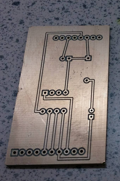
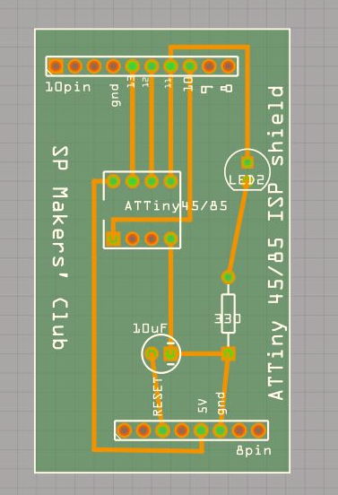
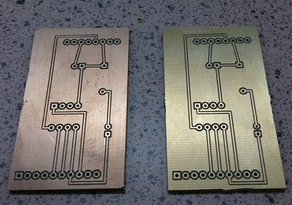
From the previous step, it is not difficult to notice something is amiss from the foot print of the PCB relatively to the size of the electronic schematic, and also the number of holes need to be drilled. In this guide, a non-conventional method will be used to generate custom small foot print PCB for Arduino that fits like a glove. The three diagrams below best describe the process of digital fabrication of a custom foot print Arduino shield PCB from software to physical prototype. The diagram on the left is the final design of the custom foot print PCB with this cheat’s method. The gerber file from the PCB design is then used to produce a prototype with the PCB milling machine, the sample is the center diagram. Lastly the diagram on the right describes the operational custom foot print PCB Arduino shield.   
  1. In this guide, the same electronic components as assumed as per the previous step.
  2. The wiring between Arduino and the rest of the components are not connected in the “schematic” tab.
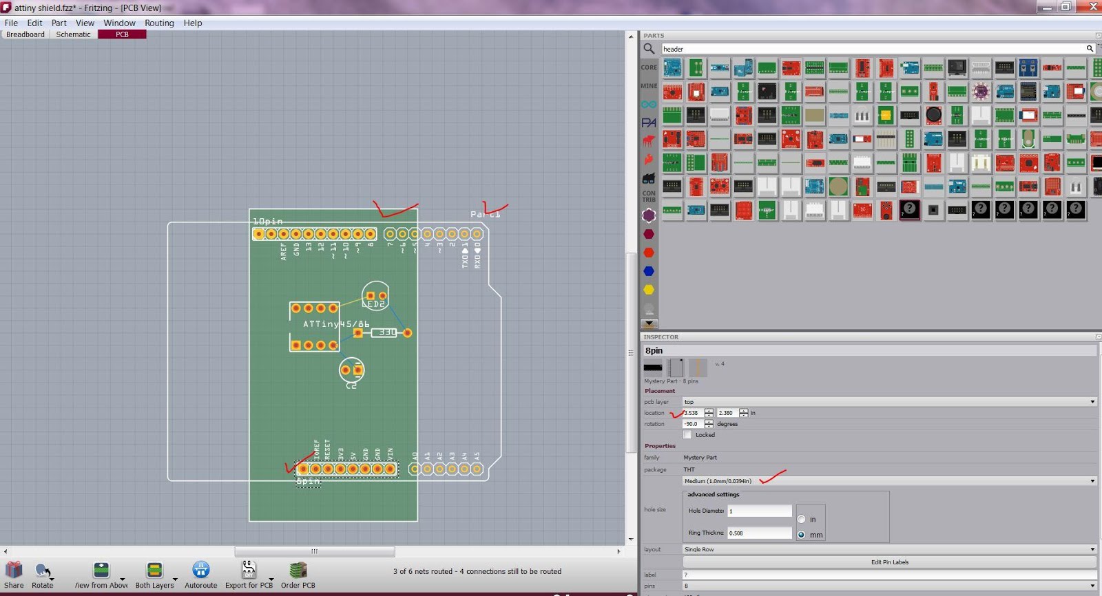
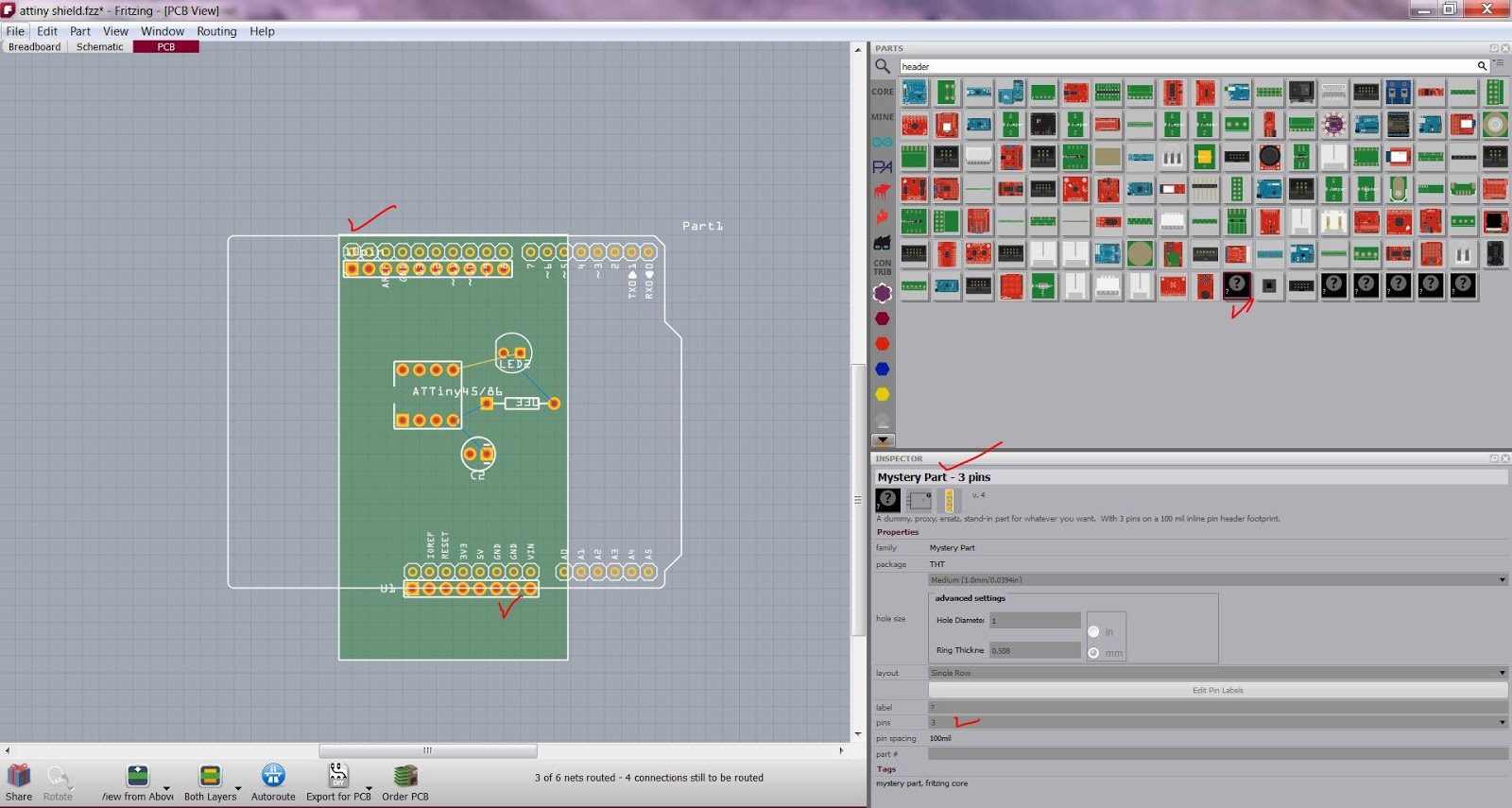
  3. From the “Parts” window panel, add the customizable “mystery part – 3 pin” into the PCB tab. This “mystery part – 3 pin” can be customized accordingly to the number of pins required by the design of the PCB. In this example, two rows of custom header of 10 pins and 8pins each are added. The following diagram describes the use of “mystery part”.
  4. Using the unconnected Arduino as a reference template, overlap with the 8pin and 10pin “mystery part” correspondingly. This shall give the relative position of the pin headers on the custom foot print PCB to the actual Arduino.   The
  5. Connect the routes as per the previous step from the electronic components to the “mystery parts” as if it is the Arduino. Once completed, delete the reference Arduino.
  6. Now a custom foot print PCB as Arduino shield is ready. The net effect is the savings on the unit cost and time taken to produce this shield commercially.
References
  1. Fritzing help and tutorials http://fritzing.org/learning/
  2. Gerbv, a gerber file viewer. http://sourceforge.net/projects/gerbv/

Sunday, January 5, 2014

Setting up the hardware for using Arduino as the In System Programmer (ISP) to download program onto ATtiny85

Setting up the hardware for using Arduino as the In System Programmer (ISP) to download program onto ATtiny85
Parts Needed
1x Arduino Uno R3
1x Breadboard or 1x Veroboard
1x ATtiny85 (or ATtiny45)
1x 10uF 25V electrolytic capacitor
1x 220ohm watt resistor
1x LED
  1. The following electronic circuit schematic describes the wiring of an Arduino to program an ATtinyXX chip. The LED and Resistor in the circuit are good to have, but not necessary. Warning: Orientation of the ATtiny85 chip DIP8 package relatively to Arduino is important during wiring.
  2. There are four possible choices of wiring up ATtiny85 chip to Arduino, each with its advantages and disadvantages. In this how to guide, the two most commonly used methods by enthusiast will be discussed.
    1. Breadboard
    2. Veroboard
    3. Printed Circuit Board (PCB) custom milled
    4. Printed Circuit Board (PCB) commercialized
Setting up the hardware with BreadboardThis method is the easiest, effortless, least time consuming of the whole lot of methods. However, it comes with a few caveats. Question: What is the disadvantage of using a breadboard?
  1. Make sure Arduino is unplugged from USB when wiring.
  2. Refer to the schematic given above, wire up the Arduino and ATtiny85 accordingly.
  3. The following diagram describes the wiring on breadboard
  4. The ATTiny85 chip is now ready to be programmed.  Refer to the how to guide “Setting up the software for using Arduino as the In System Programmer (ISP) to download program onto ATtinyXX” for the steps.
Setting up the hardware with Veroboard
This method is slightly challenging from the breadboard method. Skills require to make this veroboard is soldering, understanding of electronics principles, and also troubleshooting methodology.
Question: What are the advantages as compared to the breadboard method mentioned above?
  1. Prepare a piece of veroboard that is 20 columns wide horizontally.
  2. Align the components such as female header pins, 8pin DIP chip holder (for ATtiny85 chip), capacitor, LED, Resistor, and jumper wires with Arduino Uno R3 accordingly to the schematic given above.
  3. Solder the components to the veroboard.
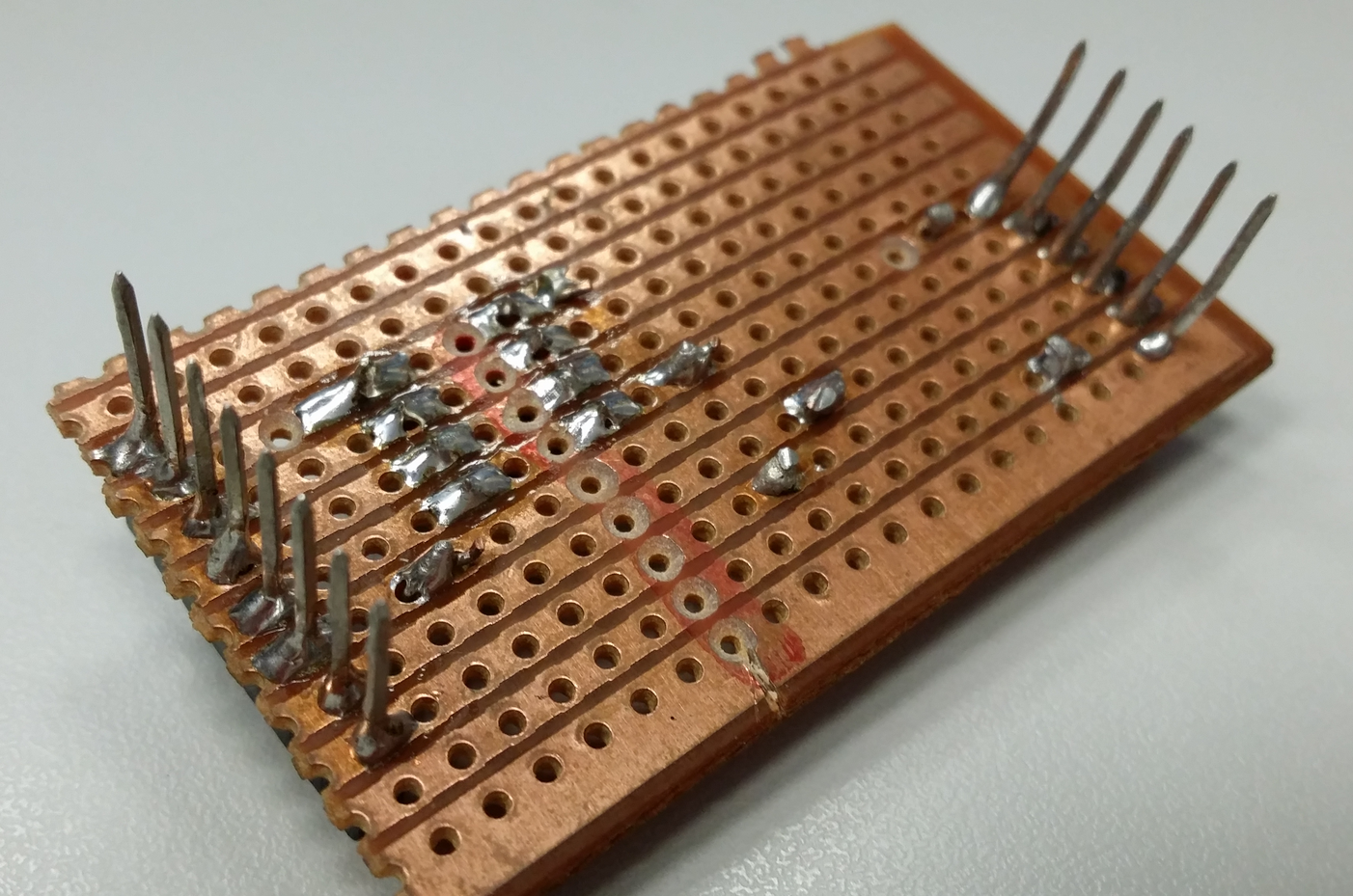
  4. Refer to the following diagram for the reverse side of veroboard, i.e not the component side.
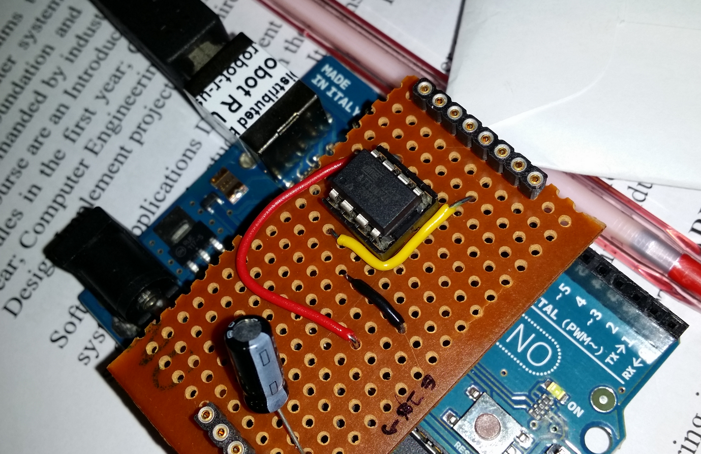
  5. The following diagram describes the veroboard ready for programming ATtinyXX chip.
  6. The “shield” (veroboard soldered with components to be used with Arduino) is now ready to be used to program an ATTinyXX chip.
Parting Notes:
Congratulations for making thus far!! You are now equipped with the necessary know how-to knowledge to quickly prototype an electronics circuit, and also making the circuit robust under unfriendly operating condition. The journey from schematics to breadboard and then to the veroboard is not the end; it is a starting point to an even more exiting journey of making your very own PCB. Allow me to put a teaser or two on the PCB making skills you are going to acquire in very soon into the future. See you at the other side of the rainbow.
References


ATTiny XX for Arduino 00XX


Saturday, January 4, 2014

Setting up the software for using Arduino as the In System Programmer (ISP) to download program onto ATtiny85

Setting up the software for using Arduino as the In System Programmer (ISP) to download program onto ATtiny85

Step0: Install ATTiny Cores
NOTE: This Tutorial assumes Arduino v1.0.x and above has been installed on the computer.
Go to this URL https://github.com/damellis/ATtiny/archive/master.zip and download this file: master.zip  
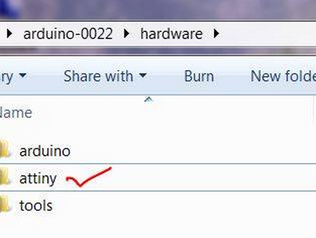
Extract this file and copy the entire folder to the “hardware” folder of your Arduino installation directory. Note: The following screen is mine and might differ from yours.
Restart the Arduino IDE programming environment. 
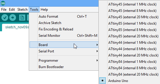
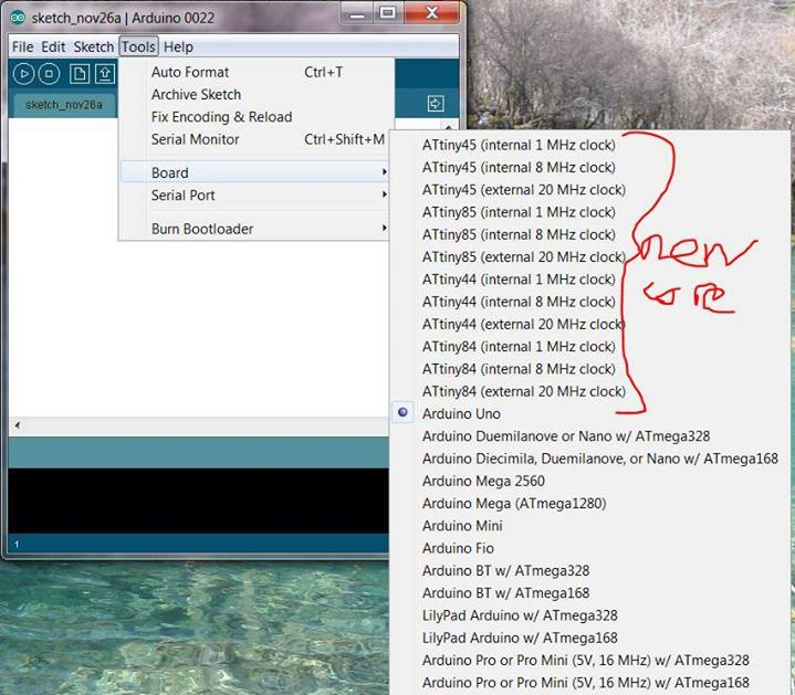
Verify the new cores (ATtinyXX series) loaded in Arduino IDE.
Note that there are also other core files for a variety of ATtiny chips loaded e.g ATting85. This page is a good starting point for interfacing with a wide range of the ATtiny or ATtiny85 using the Arduino.

Click on Tools , Board to verify the variety of ATtiny chips.

Programming the ATtinyXX chip with Arduino as the ISP
Note: This is a 1 + N step. Step 1 requires setting up the Arduino as the ISP for the first time progamming of an ATtiny. Step N has to be repeated every time to program an ATtiny. The ATtiny chip has to be placed on the ATtinyXX ISP shield, and then connected to the Arduino. The program will then be downloaded to ATtiny instead of Arduino.


Step1: Setting up Arduino as the ISP
  1. Connect usb cable to Arduino
  2. Go to Tools->Board and make sure Arduino Uno is selected.
  3. Make sure that the correct serial port is selected.
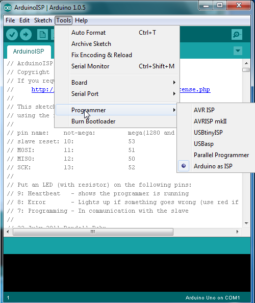
  4. Go to Tools->Programmer -> Arduino as ISP
  5. Go to Examples -> ArduinoISP
  6. Click  to upload the ISP program to the Arduino
  7. Now your arduino is ready to be used to program it's poor cousin, the ATtiny85.


Step N part1: ATtinyXX chip is inserted into ATtinyXX ISP shield; shield is then connected to the Arduino.
  1. Confirm USB cable is unplugged from Arduino when inserting the ISP shield
  2. Align ATtiny85 DIP8 package chip to ATtiny85 ISP shield
  3. Insert ATtiny85 chip firmly onto the ISP shield
  4. Align ISP shield to Arduino
  5. Insert ISP shield firmly onto Arduino
Question: What is the model of the ATtiny chip in the picture above?
Note: ATtiny45/85-PU is 20MHz (with external clock). refer to the datasheet at References.

Click here for highres picture
https://www.dropbox.com/sc/bo8yblnevzrf1vu/KrTsbTAOBU


Step N part 2: Download your programming code to ATtiny85
  1. Confirm chip, shield, and Arduino is plugged into USB.
  2. Select the corresponding code of choice (e.g *.ino) file to be programmed onto the ATtiny85 chip by clicking File-> Open.
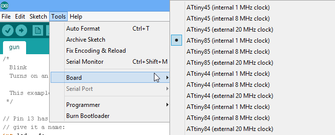
  3. Go to Tools -> Board and make sure this time you choose ATtiny85(internal 1 MHz clock)
  4. Click  to upload the program.
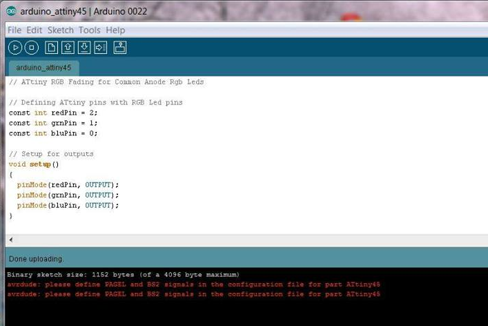
  5. Upon success, you should see the message below. Ignore the warnings. The ATtiny chip has been programmed.
  6. Observe the output of the operational ATtiny85 programmed with the code specified.


NOTE: by default ATtiny85 comes with 1MHz clock internal. This clock can be modified to 8MHz internal by the selecting option "Burn Bootloader" while selecting the option "ATtiny85(internal 8MHz clock)". Subsequent programming of ATtiny85 need to choose the board option "ATtiny85(internal 8MHz clock)"
References


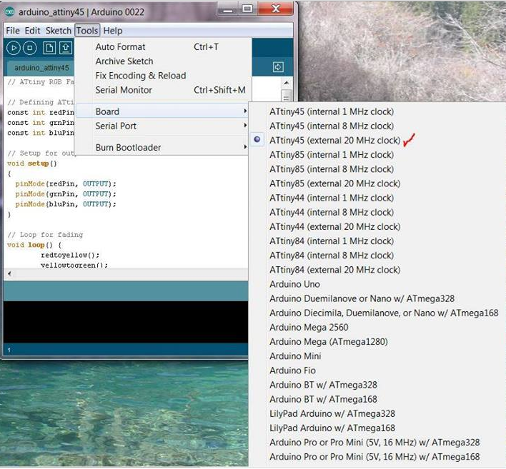
Addendum: Old version of Arduino, e.g Arduino 0022


New ATtiny cores eg ATtiny85 on Arduino 0022


Select ATtiny45-20PU as the board (requires external oscilator to function at 20MHz)


Download RGB LED code to ATtiny45

Wednesday, December 4, 2013

[CC] resize hard disk by expanding the capacity of a CloudStack 4.2 virtual machine in XenServer 6.2

Often in a given scenario of use case, the practitioner would perform some capacity planning and cater for the computing resources needed at a slightly higher amount, to give some buffer or leeway. However, we might run to an event where the computing resources is over subscribed. In the setup of the management server for CloudStack 4.2, we might run to an event that requires the engineer to increase the hard disk capacity for both the primary and secondary storage. Assuming having to physical access to the physical blade servers, adding more hard disk capacity can be as simple as plugging more hard disks. provisioning gets complicated when storage is virtualized, and with the virtual machine created in the hypervisor with XenServer 6.2.

The following steps are necessary to resize by increasing the hard disk capacity of a virtual machine residing in XenServer 6.2 as the hypervisor.

First, power off the VM. I like to create a backup of my VM before I perform anything drastic. At such, any awkward situation that requires a save, the backup is to the rescue. To resize hard disk of the VM, From XenCenter, select the corresponding VM and click properties. Change the size of the hard disk accordingly. Here the size is increased to 28GB.


Then, restart the corresponding VM. From here, we will be using the "fdisk" commands on centos6 to manipulate the VM's resources.

Take a look of the VM's hard disk with "fdisk -l" or "fdisk /dev/xvda"


Observe the total capacity of this newly resize hard disk, and also the location of the device created. note that in centos6, /dev/xvda2 is not automatically resize to the new capacity.
The trick here is to create a new primary partition called "/dev/xvda3", and then allocate the subsequent capacity form 1046 onwards to 30064771072. All these can be done with the "fdisk suite of command". use the "m" for the menu of the fdisk.


After creating the new partition, verify the new partition. All these are not done yet. The partition tables need to be written out.


This is not the end of resizing the hard disk for a VM in XenServer 6.2 hypervisor yet.


The unique-ness of centos6 as compared to ubuntu when it comes to disk management, centos6 requires the linux volume group "VolGroup" to be extended with the new physical device "/dev/xvda3". then the centos6 "home" folder that is residing at "/dev/VolGroup/lv_root" need to be extended with the newly acquired physical volume.


note the +20G parameter used caused some errors, because of insufficient disk blocks.

That is not the end of it yet. The file system is not updated with the latest disk capacity and need to be resized with command "resize2fs".


A final check to ensure the newly created hard disk capacity is available.

Tuesday, December 3, 2013

[CC] your own private cloud with cloudstack4.2 xenserver6.2 on minimal hardware

There are scenarios that would benefit from the use of a private cloud.

In a hypothetical situation, I have a bunch of data that is deemed privileged, worthy only on a private cloud. The data need to be sanitized, polished, processed, and finally visualized. The data is too hefty to be process on my laughing stock (i7, 8GB ram, 500GB hdd, on a 32bit OS), and it requires some very serious computing horse power to be leveraged on; using very popular open source, scalable, and distributed computing methodology, such as Apache Hadoop. I could follow the "how" on setting up for my thesis project using Apache Storm running off many virtual machines (VM) hosted on public cloud Amazon Web Services (AWS) EC2; all in all risking of data leakages (from human error).

Definitely need to push out the boat on setting up a private cloud for such scenario. However, the luxury of having a cloud computing center aka data center at yours disposal (yours truly is indeed privy in this), is out of reach to many.  Very much like the previous mentioned, it is the need to experiment the performance of a software on many virtual machines require cloud computing, privy data just made it a private cloud. The lack of access to data center however, should not be the hampering factor to write some interesting algorithms to be used on a distributed computing infrastructure.

In another hypothetical scenario, you may have only a single high performance blade, but the department staff requires access to this computing power on an ad hoc basis. In the good old days, staff would block off the physical blade for a time frame, install whatever software that is necessary to run the task and wipe out of after use. This methodology however come with a few caveats. For starters, lets think through a few of them. 1. assuming the full computing capability of the blade is not harnessed by 1 staff's software. 2. the blade is mutually exclusive, blocking other staff from accessing the computing power. 3. virtualizing the blade itself is not sufficient, staff's computing requirement is elastic. There must be a way for staff to manage their own virtual machines. Stemming from this 3 points, a cloud computing infrastructure fits the bill. whether to make it a public or private or hybird cloud, it is up to the department's plan for the lonely blade server.

The questions come begging: how to setup a private cloud?!
Using the open source stack for cloud computing such as Apache CloudStack, OpenStack, OpenNebula 

two software components at the minimum
1. cloud infrastructure management, in this example, the CloudStack4.2
2. hypervisor aka virtual machine monitor (VMM), in this example XenServer6.2

two "hardware" component at the minimum
1. a "computer" to run the CloudStack4.2, for managing the VMs.
2. a "computer" to run the XenServer6.2, for provisioning the VMs.

I double quoted the "computer" due to the way this private cloud experiment is setup. I have adopted a virtualized hypervisor, which is the Xen-In-Xen feature courtesy of XenServer6.2, and also a virtual machine to run CloudStack. So, I do not physically own any "hardware" for my private cloud setup. cool huh!

Each of the components and it's associated procedure to setup is worthy of a post by it self. There will be more post in the future, detailing the setting up of CloudStack4.2, XenServer6.2, administrating the VMs, and also my attempt at virtualizing a hypervisor in a virtualized hypervisor, the Xen-In-Xen-In-Xen approach. It sounds pretty much "inception-ish" attempt! 

Before we go into the gruesome details of setting up a private cloud, some dangling carrots (screenshots of my private cloud setup) 


using cloudstack to launch a VM, follow by SSH into the newly created VM.


7 easy steps to launch a VM from cloudstack.


dashboard of cloudstack