Showing posts with label digital fabrication. Show all posts

Friday, December 18, 2015

Lightsaber ala over-easy

running short of time to make a lightsaber to bring along to the cinema to watch the latest installation of starwars? fret not. you will make your own lightsaber in about 30 minutes or so and still able to make it in time to rescue princess leia. 
many years back, yours truly have made a DIY lightsaber with a differnt methodology, URL here http://www.instructables.com/id/DIY-light-saber-for/
In this guide, we will be making a lightsaber ala over-easy; we shall address the electromechanics needed to build a lightsaber with surpluses from previous project. The design of the lightsaber holder deserves an i'ble by itself.
lightsaber over-easy is de-constructed as per the following parts needed
1. a diffuser. In this i'ble i have used 5mm OD side glow fiber optics inserted into a 10mm OD acrylic tube.
2. a light source. There are 2 flavours here. one with a 3W blue LED, and the other with a lightsaber holder look-alike torchlight.
3. power supply. 5V from a mobile power bank made with 18650 cells or coin cells.
4. 3D printed holder of some sort to bind the diffuser, the light source, and the power supply.

a 5V USB power bank is used as the power source to turn on a blue 3W LED mounted on a heat sink.
Assuming the forward bias voltage is 3.3v, and ideal current of 350mA, i would need a 4ohm 2W resistor. I only have a 10ohm 2W resistor handy.
to construct the light source, these are the items used
1. small veroboard
2. 1x USB male connector
3. 1x 3W LED (BLUE) mounted on the heatsink, collimator (focus beamacr) is optional
4. 1x 2W 4ohm resistor
5. 1x usb mobile power bank made with 18650 cells
*note: the 3W LED and resistor get hot after several minutes of play.
The force must have led me to discover this lightsaber holder look-alike torch light that was well hidden deep inside the goods cabinet in the local hardware shop.
The acrylic tube inserted with the sideglow fiber optics is connected to the lightsaber holder look-alike torch light with a 3D printed adapter.
Link to the 3D model of the lightsaber adapter herehttps://www.tinkercad.com/things/2pGvKJvmqpj
check out the pictures for a detail description on the assembly


Do or do not, there is no try.


Friday, July 25, 2014

techno mohawk, maker faire, arduino, ATtiny85, WS2812 RGB LED


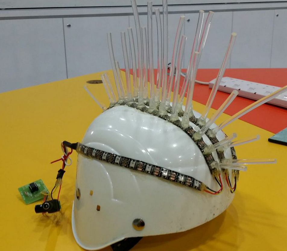
yours truly has devised this Q&D contraption for singapore mini maker faire #SMMF2014

Check this previous post on how to use Arduino, ATtiny85, WS2812/2811 RGB LED strip http://shin-ajaran.blogspot.sg/2014/04/wearable-electronics-arduino-x-attiny85.html

The contraption below use almost similar components, except the fiber optic 5mm strands as mohawk.

Wiring of this contraption is as per the following diagram.


The following diagram describe the crafting of this contraption.


video here


code here

Friday, July 4, 2014

3D printing with wood filament

3D printing with wood filament
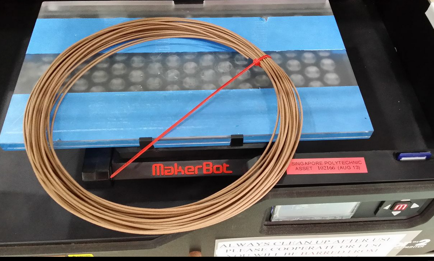
This week the wood filament by laywood is explored for 3D printing using makerbot replicator2. 3D printing in wood offers a new range of application.  Experimentation with this new medium to explore the possibilities of what can it used for. The beauty of this wood filament, it can be post treated as per the usual wood working, sanding included.
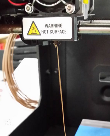
Loading of the wood filament into makerbot replicator2 for 3D printing is a breeze. Check out the previous post of modifying the loading mechanism http://shin-ajaran.blogspot.sg/2014/04/3d-printing-using-ninjaflex-with.html
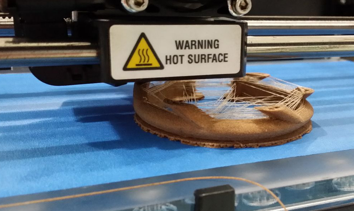
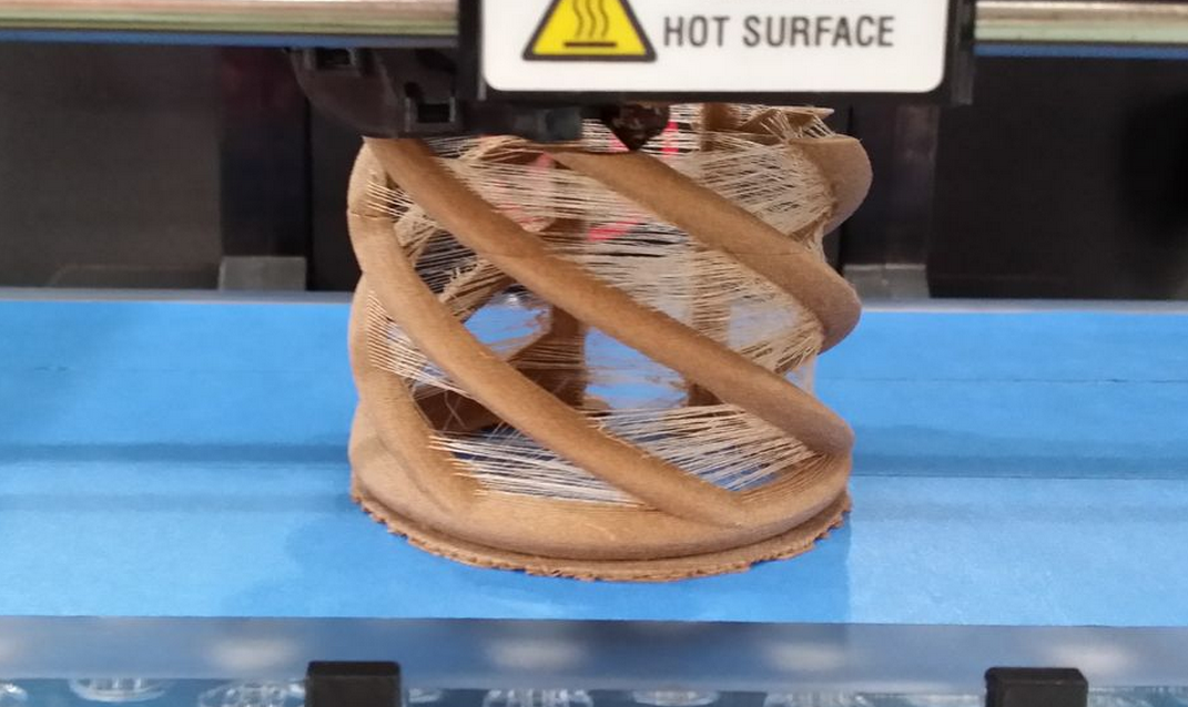
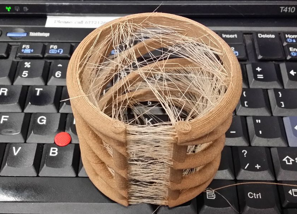
Standard PLA setting from makerware is used, but the temperature is set to 180degC instead of the usual 210degC to explore the texture and colour of the 3D printed parts. “Oozing” is observed from the 3D printed parts. Oozing in this context refers to the web of fine threads hanging from wall to wall of the model akin to a spider web. It has a term for it: “oozing while printing”.
Further refinement of the speed of filament extrusion/retraction, speed while extruding, and speed while travelling need to be tweaked to achieved a “cleaner” 3D printed parts.
A challenging model to print without support, due to the overhangs that are spiralling up.

This is the final output is plague with “oozing while printing”. Mentioned earlier, tweaking of the movement speeds of the 3 parameters are still waiting to be tweaked to perfection.

This website http://reprage.com/post/37966750340/how-do-i-stop-plastic-from-oozing-when-3d-printing/ offers some suggestions such as lowering the temperature of the hot end, reducing the movement speed, and increasing the retraction length. All the above requires time to discover the best settings!

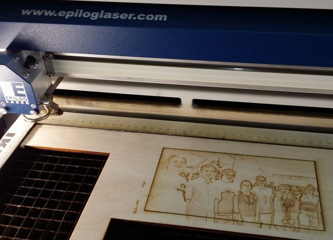
Engrave photo on wood with a laser cutter

Engrave photo on wood with a laser cutter
A photo or image can be realized on a piece of wood with the use of laser cutter. The process is simple. First, the photo has to be digitally manipulated. This photo is then sent to “print” via the laser cutter using popular vector drawing software such as coreldraw.
To digitally manipulate the subjects composed in a colour photo, popular vector drawing software such as coreldraw (proprietary), inkscape (open source) can be used for manipulating it into greyscale, and then subjects are outlined in black. The varying shades of grey, and black outlines determines how much power the laser cutter should output to engrave the piece of wood via the “rastering” mode. The darker the region, the more power will be output to “engrave” the wood by burning parts of it.
In FabLab@SP, 3 laser cutters are available; The Epilog, The Rayjet, and the HAS. The general steps to engrave photo are similar, but the parameters to set for laser cutting associated to different type of laser cutters are slightly different.
Parts needed
  1. A piece of wood; balsa, plywood will do. Preferably 3mm or 5mm.
  2. Access to a laser cutter. This guide assumes access to the epilog laser cutter
  3. Access to a vector drawing software, or photo manipulating software such as adobe photoshop, coreldraw, inkscape, etc. In this guide, an online photo editor www.ribbet.com is used.
  4. A photo of choice.
Step1: upload photo to be edited to www.ribbet.com
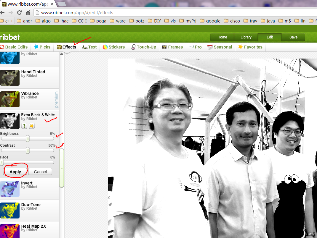
Step2: Click on “effects”, then scroll to “Extra Black&White”. Manipulate the 2 sliders “Brightness” & “Contrast” to achieve the desired outcome as per depicted in the following diagram. Desired outcome to be achieved can be defined by “high contras on specific features, such as facial features of the subject(s)”, “white-out background to give a strong highlight on the subject”
D:\Users\s41764\Desktop\laser cut stuff\ribbet1.PNG
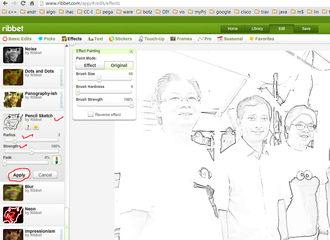
Step3: Still in “effects” tab, scroll to “pencil sketch”. This effect will highlight outline the subjects as per the black & white photo, by giving a darker shade of grey at the edges. Manipulate the sliders “radius” and “strength” until the subjects are “standing out” from the background and gives a lasting impession.
D:\Users\s41764\Desktop\laser cut stuff\ribbet2.PNG
Step4: save the manipulated photo on the computer as *.JPG.
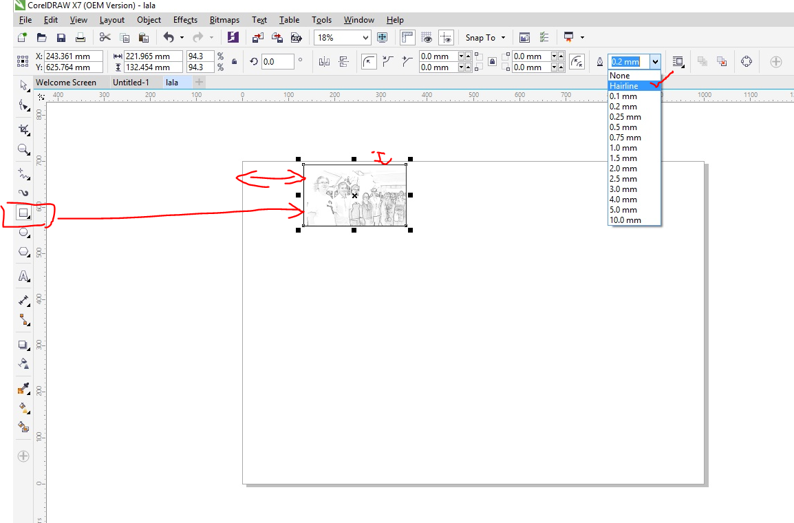
Step5: On the computer that is connected to the laser cutter, use coreldraw to create a new canvas of the type “fusion table”. Open the manipulated photo in coreldraw, position the photo such that it corresponds to the piece of wood where it will be laser cut. Select the box drawing tool on the LHS and enclosed it on the picture. Then select the line thickness of the box to be “hairline”. This setting corresponds to cutting a box shape surrounding the photo. The following diagram explains it all.
Step6. Load the piece of wood into the laser cutter
Step7. It is crucial to ensure the canvas chosen for laser cutting is of the type “Fusion Table”. File-> print OR Press on the “print” logo. A popup box will then appear. Ensure that the printer is “Epilog” and not your regular paper printer, and then click on preference to modify parameters that are essential to the quality of the laser cutting output. The following diagram illustrates it.
Step8. Select laser cutting parameters such as thickness of the material, job type, speed, power, and frequency and then press “OK”. Each of the manufacturers has meted out recommended settings to the parameters in a lookup table form for different type of material. In this guide, a 5mm thick plywood is used. Assuming the output of this laser cutting is very faint or hardly noticeable, it is recommended to crank up the power and lower down the speed. Otherwise if the output of this laser cutting appears to be burnt at the edges.
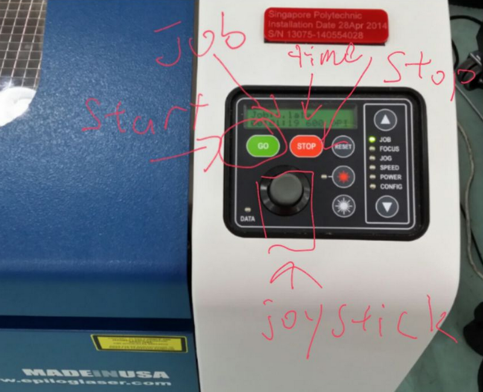
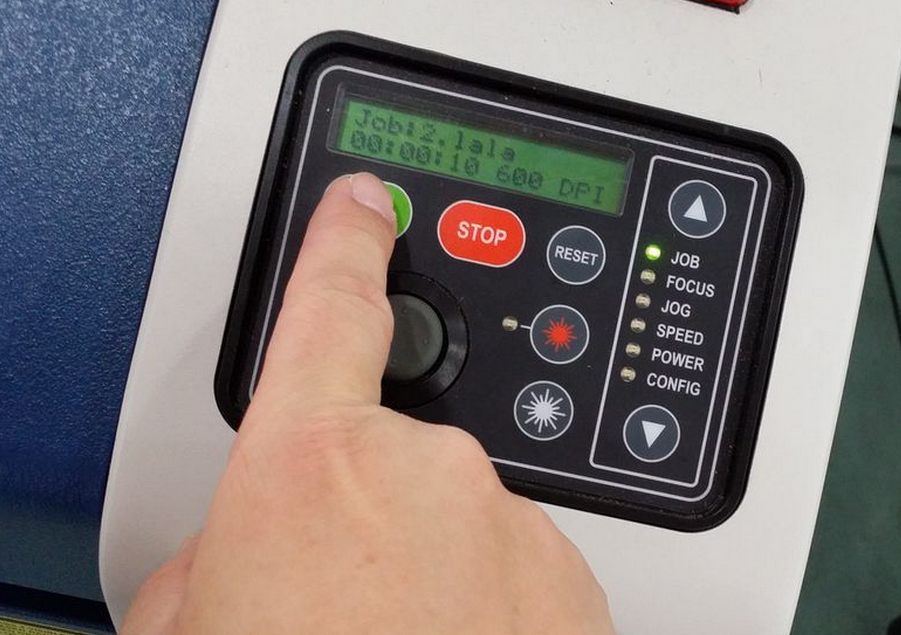
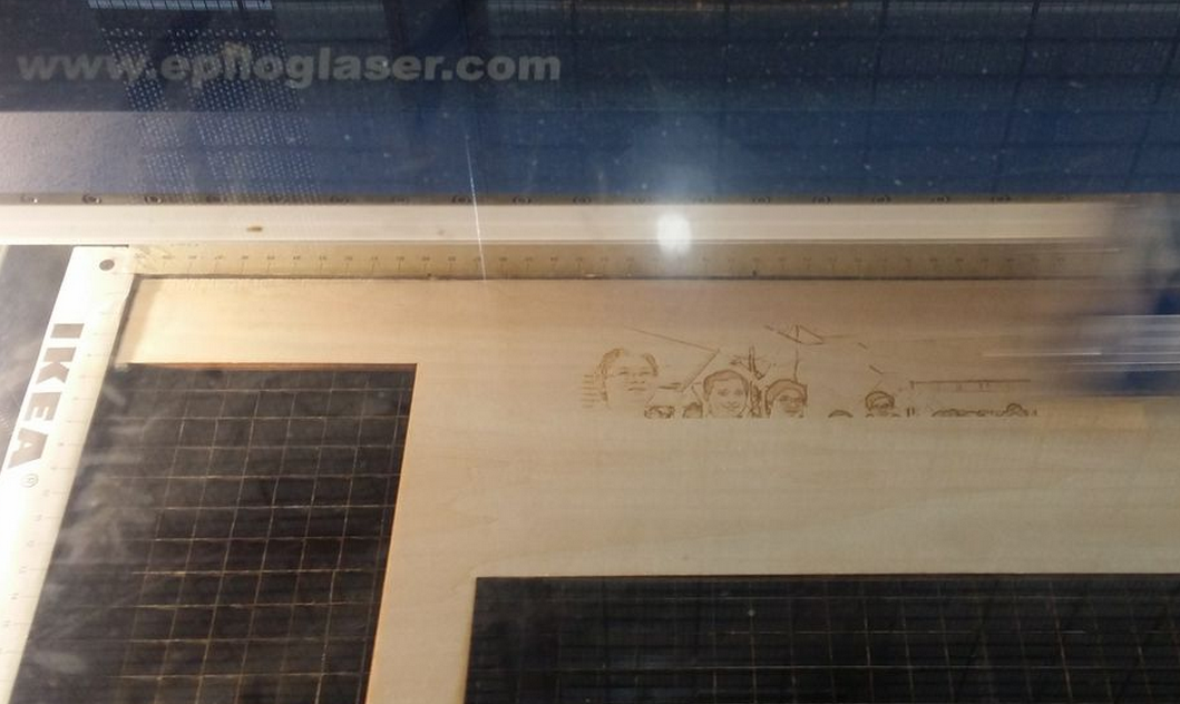
Step9: Close the protective cover of the laser cutter with the wood properly aligned in it and then press “GO” on the control panel. Observe the magic!
Brought to you by FabLab@SP

Friday, April 18, 2014

3D printing using NinjaFlex with Makerbot Replicator2 and RepRap Prusa Mendel i3 Durbie v2

3D printing using NinjaFlex with Makerbot Replicator2 and RepRap Prusa Mendel i3 Durbie v2

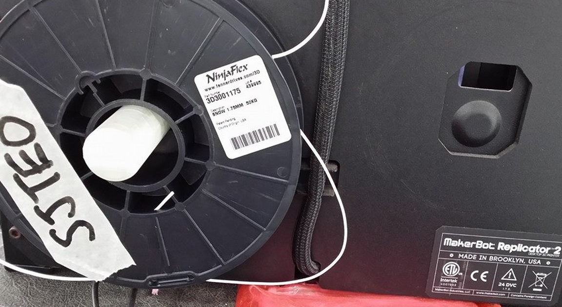
Earlier in February, yours truly came across an exciting new type of 3D printing filament that is flexible, stretchable, thus allows for many creative creations. Say farewell to the rigidity of PLA and ABS! Without hesitance, yours truly ordered a spool of 1.75mm white filament with a local vendor (probably the first spool brought in here) at SGD100 per pop.
May I present to you, the NinjaFlex by Fennel Drives http://www.fennerdrives.com/ninjaflex3dprinting/_/3d/ .
Finally over the last few days, yours truly manage to find some time to play with this excellent new type of filament. Prior to commit, it is best to read the manufacturer’s website and adafruit’s tutorial, and by following the recommended best practices for 3D printing with this NinjaFlex should be a breeze. Technically I summarized from the reading materials, if I followed the recommended extruder temperature of 215degC, non heated bed, and blue tape on the printing bed; it is going to be minimal effort to install the NinjaFlex and we can have a lot of creative fun happening here at FabLab@SP.
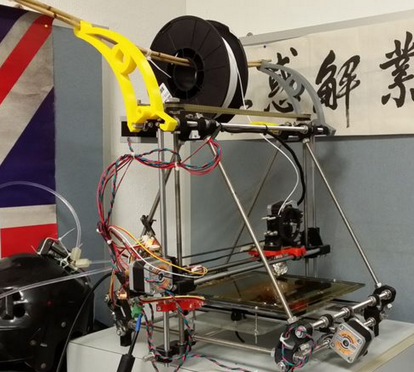
Sorry to throw in the wet blanket. The experiment with NinjaFlex is not a breeze, even with the prior knowledge well versed; hence there is a need to raise some awareness and share some experience on how to get it right (or way wrong) with NinjaFlex. Courtesy of FabLab@SP, yours truly has the luxury of tens of makerbot replicator2 at his disposal, and a well-stocked personal arsenal; you guess what, it consist of a 3D printer the RepRap Prusa Mendel i3 Durbie v2
Few important parameters that decide the success rate of 3D printing with NinjaFlex: filament feeder mechanism (FFM), extruder hot end (EHE) temperature, heated printer bed (HPB) temperature, type of tape used on printer bed, and extruder extruding speed (EES). Gathering from the reading material over the Internet, NinjaFlex has a specific operating temperature; users reported success with EHE set at 215 to 225 degC, and HPB set at 30 to 50degC. The filament is flexible and stretchable, sticks well to kapton tape; others reported success on blue tape, scotch tape, and acrylic. However, due to the partiality of info provided by various users that reported success, it is difficult to replicate their success at our end.
Hence yours truly has done several A/B test for NinjaFlex on both makerbot replicator2 and reprap, and varying the parameters.
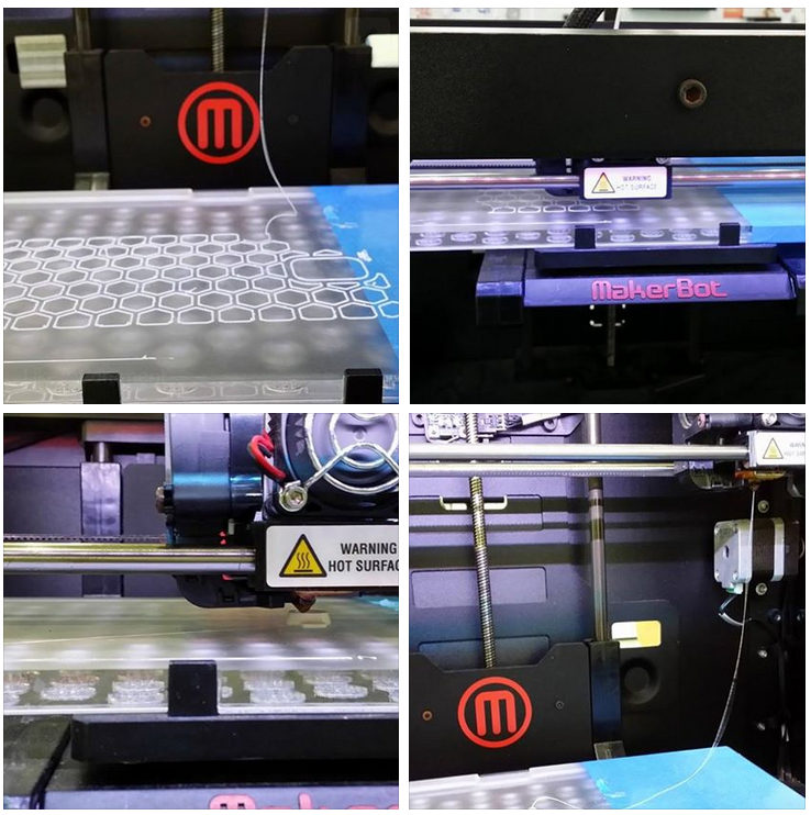
Experiment1: NinjaFlex 3D printing with Makerbot replicator2 using modified MK2 FFM, non HPB, blue tape on printer bed.
All the makerbot replicator2 in FabLab@SP are modified with spring loaded FFM, as depicted in the picture above. Spring loaded FFM is the must have to print NinjaFlex on makerbot replicator. All parameters such as EHE at 218degC, non HPB, blue-tape on printer bed, EES at 40mm/s are held constant. On first try or maybe it is beginner’s luck, NinjaFlex is loaded successfully, FFM is feeding NinjaFlex with no qualms during loading phase. Next, when it comes to 3D printing with NinjaFlex, the material refuses to stick on the existing printer bed with blue tape, thus excess material clogged the nozzle. Subsequent tries to print, no material is oozing from the nozzle. So, carry out the SOP of unloading the filament, and then clear any material that clog the hot end or drive gear chamber. The next many hours to reload the NinjaFlex are frustrating. First of all, the filament itself is limp, lack the stiffness of PLA, thus it is becoming increasingly difficult to fish the filament through the guide hole. Even though the filament is fished properly through the guide hole, but no material is extruded through the nozzle. The filament is fed continuously in the whole process alright, but somehow, nothing is extruded. Open up the extruder to check for any jammed material at the hole entering the hot end, nothing. So basically the couple of hours are spent on repetitive cycle trying to load the NinjaFlex. The next logical step is to observe ninjaflex filament feeding into the extruder without the heat sink and fan. Surprise!! The filament is winding up in the drive gear. So to conclude this experiment: ninjaflex does not stick to blue tape, filament is too limp to be fed 100% correctly.
Experiment2: NinjaFlex 3D printing with RepRap Prusa Mendel i3 Durbie v2, HPB, kapton tape on printer bed.
All parameters such as EHE at 218degC, HPB at 40degC, kapton tape on printer bed, EES at 40mm/s are held constant.
Due to the design of the geared extruder, loading the limp filament is a breeze compared to makerbot replicator2. All need to be done basically to loosen the 2 spring loaded screws, manually fish the filament through the guide holes and also into the hot end, tighten the screws and then extrude filament to check for proper feed.
On the first try to print, the ninjaflex did sticks very well indeed to kapton tape. Besides kapton tape, subsequent tries on HPB’s glass plate but without kapton tape sticks well too.
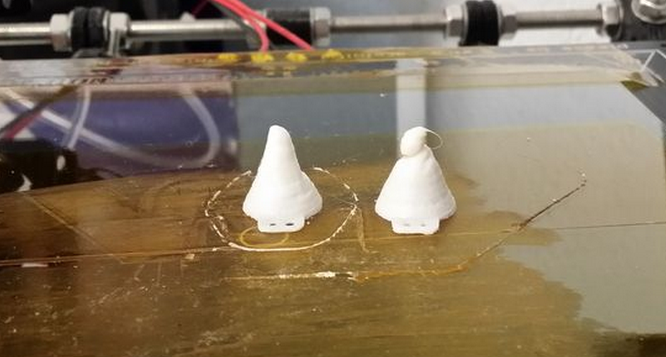
3D Printing win NinjaFlex using RepRap went well. All is left is to fine tune the parameters to achieve the ideal result. Cone on the right is first try, left is second try.
Once the 3D printing parameters are tune with confidence, try it on a bigger print job to check whether 3D printing NinjaFlex with RepRap lives up to it’s reputation. The parameters used are EHE at 220degC, HPB at 40degC, kapton tape on printer bed, EES at 20mm/s. The following parameter is peculiar only to slic3r for ninjaFlex: Fill pattern rectilinear, Infill 50%, 3 shells, 4 skirt loops, layer height 0.2mm,
The first few layers printed according to expectations, however, half way through a 3hour print job of a note3 bumper, the ninjaflex filament is not feeding and starts to air printing. After a few tries with the smaller test prints, apparently the nozzle clogs at random layers and hence air printing too.
While issuing a new test prints, out of sudden the reprap is not printing and pronterface can’t connect to the reprap. First, the ninjaflex is working only to air print randomly, then the reprap stop responding. The experimentation with NinjaFlex on reprap can’t be continued, until the issue with RepRap is resolved. What a bad day to do experiment. The semi conclusion will be NinjaFlex sticks well to kapton (and also glass panel tested before the RepRap went cold), printing with RepRap is a breeze; but need to resolve the air printing.
Experiment3: NinjaFlex 3D printing with Makerbot replicator2 using modified flexMK8 FFM, non HPB, blue tape on half of printer bed, and the other half is clear acrylic.
For experiment1, the suggestion is to find a better spring loaded FFM that ensures 100% chance of feeding the NinjaFlex into the hot end of the extruder. There is ready solution for open source printers, such as the lulzbot flexystruder http://www.lulzbot.com/products/flexystruder-tool-head tailored specifically for NinjaFlex type of filaments. However, not suitable for makerbot replicator2. I guess the good people at fennel drives are serious about their ninjaflex product, reads about the user comment on Internet and thus uploaded a FFM mod http://www.thingiverse.com/thing:169086/
This mod is very easy to install. Simply print out on the existing 3D printer, let it cool by turning off the power supply, and disassemble the existing FFM to be replaced with the flexMK8.
Loading of the NinjaFlex into Makerbot replicator2 could have been easier!!! It takes only a single try to load!
The parameters used are EHE at 220degC, non HPB, EES at 20mm/s. The following parameter is peculiar only to makerware for ninjaFlex: Infill 10%, 2 shells, layer height 0.2mm. As for the test print, see for yourself.
As suspected, NinjaFlex sticks better on clear acrylic than blue tape on printer bed.
Confidence are built upon many unsuccessful experiments. The first big print job that takes 4 hours to complete with NinjaFlex.
Of course, the experiment with NinjaFlex comes complete with the adafruit cyberpunk spikes
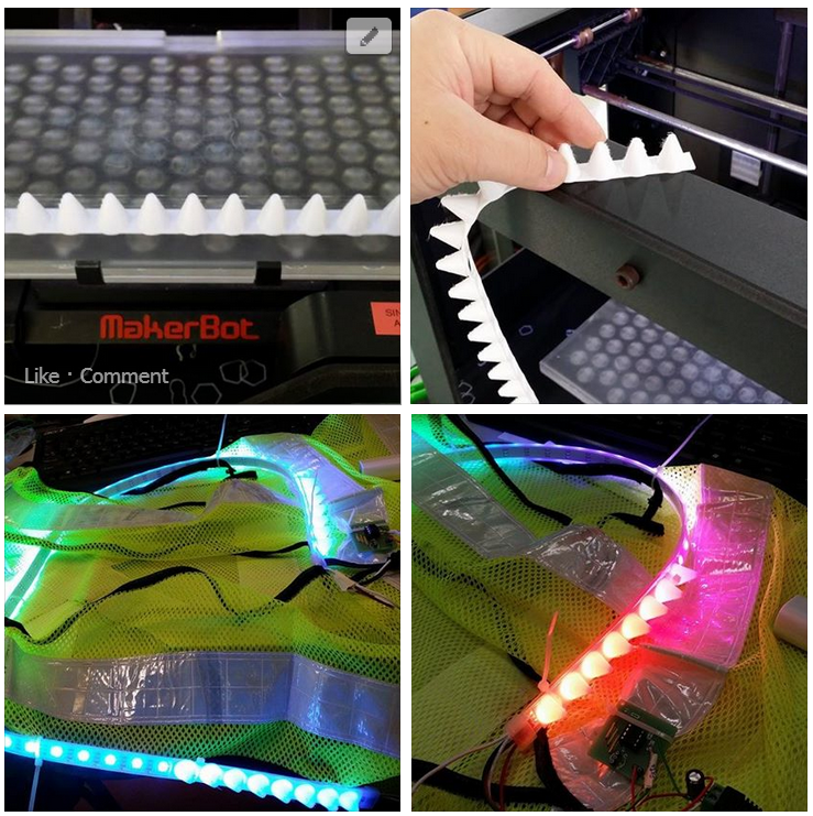

Concluding experiment3: use flexMk8 with makerbot replicator2 for a successful loading, as for the parameters used are EHE at 220degC, non HPB, EES at 20mm/s. The following parameter is peculiar only to makerware for ninjaFlex: Infill 10%, 2 shells, layer height 0.2mm.
Outstanding task: fix the RepRap and then continue to find the best parameter to print NinjaFlex.
References

Saturday, January 11, 2014

Design and fabricate a Printed Circuit Board (PCB) with Fritzing and cheat’s method to customize an Arduino shield

Design and fabricate a Printed Circuit Board (PCB) with Fritzing and cheat’s method to customize an Arduino shieldA sample screenshot of the Fritzing GUI, and a designed PCB ready to be fabricated.
Step 0: Download and install Fritzing, and familiarization with the GUI.
  1. Navigate to this URL http://fritzing.org/download/
  2. Download the Fritzing package according to your computing platform
  3. Extract the downloaded file into a folder of choice
  4. Install and launch by double clicking on the Fritzing Icon
  5. Familiarization with the Fritzing GUI. There are three tabs in the Main window panel, which offers electronics circuit in three different view. The “breadboard”, the “schematic”, and the “PCB”. Top RHS window panel offers pre-defined size of most commonly used electronics components, and also components from a myriad of vendors which include Arduino, Sparkfun, and more.
  6. The beauty of Fritzing. User can start by placing electronics components in the breadboard view or schematic view. Magically, the components will appear in the other 2 tabs that are not used. It is just a matter of preference where to start placing the electronic components.
  7. Once the electronics components are placed in the tab of choice, wiring to form the electrical connections between the electronic components can be made. The wiring connections will then be reflected in the corresponding two tabs.
  8. At the moment of writing, Fritzing does not offer simulation of circuits
Step1: Define an electronic schematic in Fritzing’s “schematics” tab
In this guide, The electronics schematic for ATtinyXX ISP shield will be assumed. While the methodology is generic, the electronics circuits should be user defined in the future use.
  1. Using the schematic above as a guide, call out the corresponding electronics components on Fritzing via the “Parts” window that is conveniently located at the top RHS panel into the “schematics” tab on Fritzing.
  2. Wiring for the connection of the components can be performed by click and hold on the point of one component, then release the click at the corresponding point of the other component. A wire will then appear.
  3. Check all wirings are done correctly and accordingly to the given schematic, in Fritzing.
  4. Now it is ready to proceed to PCB design by clicking on the PCB tab.
Step2. Design and Fabricate a PCB
In this guide, the ATtinyXX ISP shield will be assumed as an example to demonstrate the how-to of designing a PCB. A few points to note: PCB unit cost is related to two pricing components, the PCB footprint (the size of the board), and the number of layers (the copper threads layer). In other words, a smaller PCB foot print with single layer is cheaper than a bigger PCB foot print with double layer.
  1. Start PCB design by clicking on the “PCB” tab.
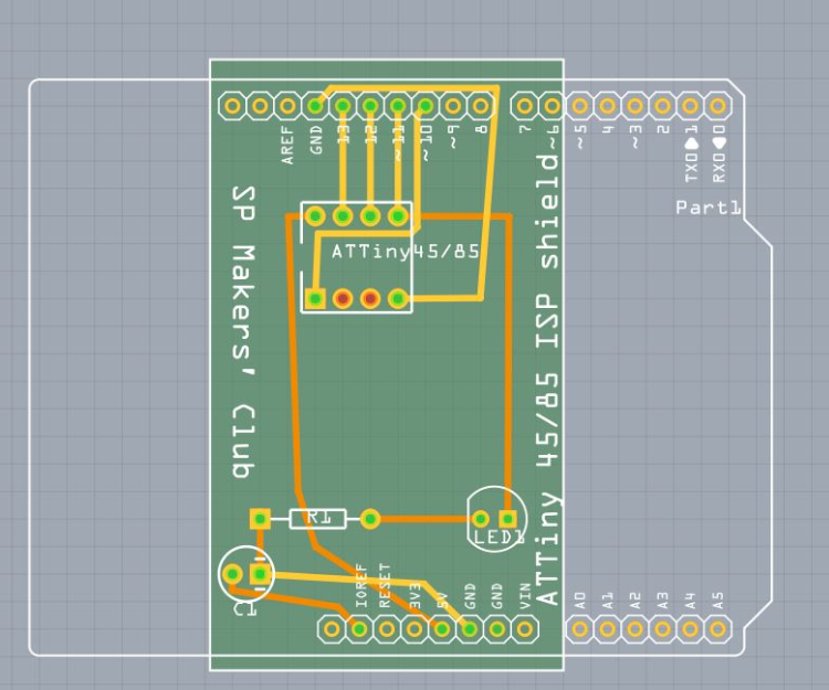
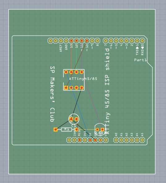
  2. The following screen shot best describes the designing process.
PCB resized and manual routes for double layer                       full size Arduino PCB foot print without routes
  1. In the screenshot above, the green box is the foot print of the PCB, the colour coded wiring corresponds to the wiring of electronic components made earlier. The human readable white colour text on the PCB is referred to as the “silk screen”, and it is customizable. The white colour shape outlines the physical perimeter of an Arduino and the relative position of the two rows of header pins. Using this predefined template from Fritzing, the to-be-created Arduino shield will fit the Arduino in a snug fit.
  2. Next is to add the routes. Routes on the PCB refer to the wiring of copper threads that connects electronic components. There are two camps or school of thoughts when it comes to placing routes on a PCB. First is the “auto-route” that requires minimal human intervention. Lastly the manual route that requires a lot of human attention. Placing of routes requires both functionality, and aesthetics. The routes must not be not too close to each other, and not overlapping to each other causing a short circuit.
  3. At any time when designing the routes in Fritzing, routes can be deleted or undo.
  4. Auto route by pressing the “Auto Route” button in Fritzing
  5. Manual route by clicking on the individual wires from one end to the other end.
  6. When route design is finalized, perform a design rule check by pressing Ctrl+Shift+D. Fritzing will recommend if the PCB design is ready to be fabricated.
  7. Export the PCB design into gerber files (RS-274X) by clicking on the “Export for PCB” button and send it to your local vendor to fabricate.
  8. The generated gerber files can be view using open source software such as gerbv.
Step3. Design a custom foot print PCB Arduino Shield using cheat’s method
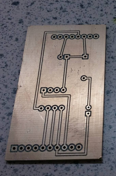
From the previous step, it is not difficult to notice something is amiss from the foot print of the PCB relatively to the size of the electronic schematic, and also the number of holes need to be drilled. In this guide, a non-conventional method will be used to generate custom small foot print PCB for Arduino that fits like a glove. The three diagrams below best describe the process of digital fabrication of a custom foot print Arduino shield PCB from software to physical prototype. The diagram on the left is the final design of the custom foot print PCB with this cheat’s method. The gerber file from the PCB design is then used to produce a prototype with the PCB milling machine, the sample is the center diagram. Lastly the diagram on the right describes the operational custom foot print PCB Arduino shield.   
  1. In this guide, the same electronic components as assumed as per the previous step.
  2. The wiring between Arduino and the rest of the components are not connected in the “schematic” tab.
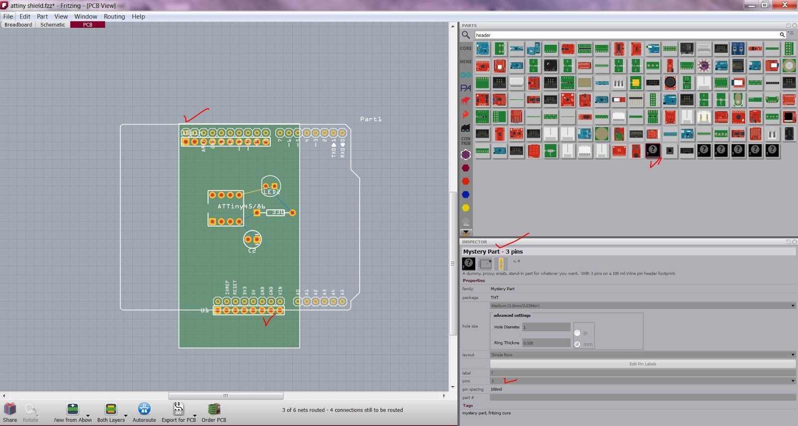
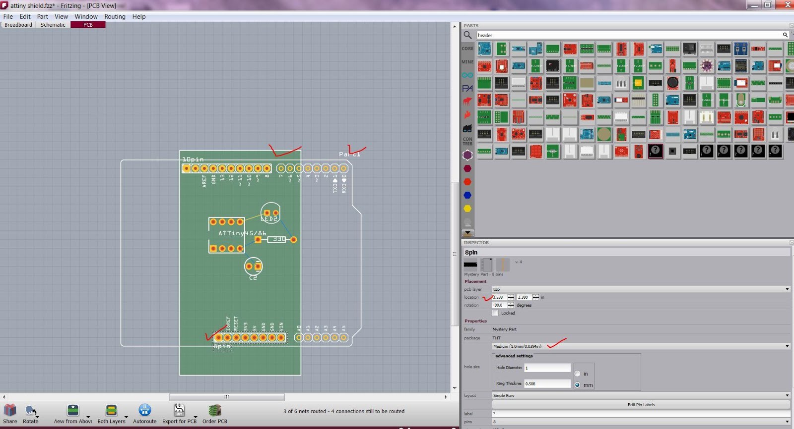
  3. From the “Parts” window panel, add the customizable “mystery part – 3 pin” into the PCB tab. This “mystery part – 3 pin” can be customized accordingly to the number of pins required by the design of the PCB. In this example, two rows of custom header of 10 pins and 8pins each are added. The following diagram describes the use of “mystery part”.
  4. Using the unconnected Arduino as a reference template, overlap with the 8pin and 10pin “mystery part” correspondingly. This shall give the relative position of the pin headers on the custom foot print PCB to the actual Arduino.   The
  5. Connect the routes as per the previous step from the electronic components to the “mystery parts” as if it is the Arduino. Once completed, delete the reference Arduino.
  6. Now a custom foot print PCB as Arduino shield is ready. The net effect is the savings on the unit cost and time taken to produce this shield commercially.
References
  1. Fritzing help and tutorials http://fritzing.org/learning/
  2. Gerbv, a gerber file viewer. http://sourceforge.net/projects/gerbv/